Section Two – High Lift Devices in Simulations
Up until now, we have looked at real world aerodynamic academic info. Next, we turn to what these devices actually do for us in our sims. Real world theory is fine…but what’s really important to us is what we can expect to get out of these features when we fly. Let’s take a pilot’s perspective look at these devices and then assess how they perform in some of our sims.
Why Are Flaps Used?
We can use flaps to improve takeoff , landing , and turn performance . Flaps do this by improving the lifting capability of the wing. Before we go any further, we need to distinguish between something that increases lift and something that increases our ability to pull more G. Both are important in flying our sims…we just need to know which applies when.
One point has to be made regarding this article. Most of the info here will be aimed at prop sims, not modern jet sims. The reason is simple. When you are turning and burning in your F-15 or Su-27, the AI will be configuring the aircraft for maximum performance. You won’t have to worry about flap selection. So…prop-heads…pay attention! This one’s for you!!
Flap use in the takeoff. In real life, some aircraft are designed to use flaps during takeoff, and some are not. Some only use flaps for takeoff under certain conditions. Don’t expect a lot of guidance in this respect from our sims. MS CFS2, for example, has a checklist feature that allows you to use a takeoff checklist to prepare for takeoff. Unfortunately, all the checklist does is tell you that you have the option of using flaps or not. Not much help, I know!. So, what kind of general advice can we use? Here it is.
Using takeoff flaps will probably not ever hurt you…as long as you stick with the “takeoff” flap setting. If your sim does not have this setting, then use the first stage, or “notch”.
In the absence of specific guidance, when should you use takeoff flaps? Basically, anytime you want to shorten the takeoff roll. Two cases come to mind. In the first, you have obstructions off the end of the runway and you want to get airborne early to climb over them. In the second case, you are carrying external ordnance that would require a higher takeoff speed than normal if you made a no-flap takeoff. Accelerating to this higher speed will result in a longer takeoff distance. Sometimes, this longer distance is undesirable. You can correct this by using a takeoff flap setting to reduce takeoff speed. The result is a shorter takeoff roll. The next figure is from the real world P-51 flight manual showing the use of flaps to minimize the takeoff roll. The objective is to clear the trees at the end!
Here is a summation of the takeoff flap guidance given to us in a few of today’s sims (modern jet sims are omitted since the AI will control flap selection):
IL-2 : The manual directs that all aircraft use the takeoff flap position.
CFS2 : The manual directs you to refer to the takeoff checklist for the type of aircraft that you are flying. Unfortunately, the checklists leave flap selection up to your discretion.
MiG Alley : Not mentioned in the manual.
Aces High : Use the web site Help section for info on flap use. Some aircraft are discussed and some guidance is provided on takeoff flap setting.
Jane’s Attack Squadron : The game CD includes a Training Section. Here you will find that flaps are to be set to 20 degrees for takeoff.
Flap use in the landing. Every fighter that has flaps will usually be using them for landing. Why? Two reasons. One, it allows a slower approach speed that results in a shorter roll out. Two, with flaps down, the aircraft has more of a nose low pitch attitude and, consequently, the pilot has a better view over the nose. As a result, landings are easier. Here are two screenshots that show this…one with flaps up and one with flaps down, same airspeed.


In these pictures, the aircraft are both in level flight at the same speed. Note that the aircraft with flaps down has the lower pitch attitude. I’ve included a forward view of each to show where the horizon line is…the effect of lowering the flaps on pitch attitude is clearly noticeable.
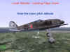
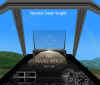
One disclaimer here. In simulation forward views, the pilot’s line of sight is still straight ahead, typically through the middle of the gunsight/HUD area. The next figure shows the typical forward view line of sight with the aircraft in level flight at cruise airspeed.

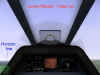
However, when flying at slow speeds, for example, when on final for the landing, the pilot will be looking down the nose of the aircraft as this figure shows.
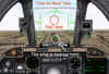
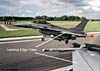
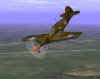
Why? Because the actual flight path of the aircraft is seen below the gunsight area. This look angle is more obvious in our modern jet sims where the velocity vector “tadpole” is included in the heads up display (HUD). In the next two shots of an A-10 on short final, you can see the “tadpole” velocity vector superimposed on the approach end of the runway. In the external, note the nose high attitude. I have flown the aircraft with no flaps to accentuate the difference in pilot look angle (tadpole) and the “normal” picture of the gunsight position often seen as the “level flight” flight attitude.


Regardless of WW2 or modern sim, the fact remains that the forward view still is locked into a line of sight that is more typical of cruise speeds than slow speeds. The typical view of “half instrument panel-half windscreen” is a poor representation of what the real world pilot actually sees when flying at the higher angles of attack seen in the landing pattern. What we need is a forward view that is aligned with the flight path …that would be far more representative of what the pilot needs and wants to see.
Note that in our newer sims that allow use of the mouse to change the forward view, mere raising of the look angle only shifts the line of sight on a line parallel to the original (as if you had raised your seat)…it does not move that line of sight down as we would want. The first of the next two views shows the normal forward view. The second shows the view using the mouse to shift the view line of sight up. The gunsight is still pointed at the same area and no additional viewing area over the nose is achieved.


One exception is how your seating position can be changed in Aces High. This sim actually allows you to get a better view over the nose by changing the view as the following shots show.

So for landing, what are the things to remember? Use flaps to lower your pitch attitude to improve your view “over the nose”. Keep in mind that the typical sim does not present a forward view that looks along your flight path line of sight. If your sim permits, try to raise your seating position to improve your ability to see over the nose.
Next, remember the aerodynamic results of lots of flaps. You get a lot more drag for not much more lift. You may need more power to hold your speed. Be careful with your speed…the extra drag will tend to slow you down quicker. Keep crosschecking your speed. Yes…your stall speed is probably lower, but the stall angle of attack is less. Your stall margins may be reduced as a result. If you stall at these speeds and with the power up, you can lose control due to torque effects or stall characteristics…so don’t get slow!
Flap use in improving turning performance. Now we are getting to the meat of the matter. In fact, I could have titled this section “What Is Possible vs What Is Practical” . What I want for you to get from all of this is an idea of how to use flaps in a practical manner that comes close to how we use them in real life. As you will see, our sims allow you to use flaps in a wide range of ways. Not all of these are “realistic”, and some of them provide no actual benefit to the sim’s flight model. Having said that, let’s begin with some general ideas.
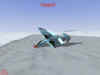
The importance of flaps in turn performance is their effect on the ability to produce extra G. All air combat maneuvering is a function of pointing the aircraft where you want it to go. To do this, you roll to orient your lift vector in the desired direction, and then you pull backstick pressure to move your nose to that point. In the next screenshot, see the FAC leaving some cons as he pulls on the pole!

However, the word “lift” in the phrase “lift vector” is a bit misleading. Lift is not what you should be thinking of. G is what will produce the results you are looking for when you want to maneuver your plane. The lift vector is, of course, defined by the magnitude of the G being pulled, but what I want to do is to take the emphasis off the term “lift” and replace it with the term “G”.
Related Posts:
Related posts:
 Secondary Flight Controls – Flaps
 Page 2
Secondary Flight Controls – Flaps Page 4
Secondary Flight Controls – Flaps Page 5
Secondary Flight Controls – Flaps
Secondary Flight Controls – Flaps Page 2
Secondary Flight Controls – Flaps Page 4
Secondary Flight Controls – Flaps Page 5
 Secondary Flight Controls – Rudder, Flaps, and Trim
 Page 4
Secondary Flight Controls – Rudder, Flaps, and Trim Page 5
Secondary Flight Controls – Rudder, Flaps, and Trim Page 6
Secondary Flight Controls – Rudder, Flaps, and Trim
Secondary Flight Controls – Rudder, Flaps, and Trim Page 4
Secondary Flight Controls – Rudder, Flaps, and Trim Page 5
Secondary Flight Controls – Rudder, Flaps, and Trim Page 6