Section Two – Trim Systems
Lateral Axis (Pitch) Trim
We’ll begin with the pitch trim feature since it’s the one pilots are most often involved with. Let’s keep in mind that we are looking at design features that affect the tail’s ability to generate a force that holds the pitch attitude where the pilot wants it. As we go through these various types, here’s one thing to remember…trim is directly related to speed changes. The greater the speed change, the greater the need for trim. Prior to WW2, the typical flight envelope in terms of speed range was relatively small. In some cases, trim was not even designed into aircraft because of the narrow speed range. But as aircraft speed capability increased, so did the need for trim. By the time we got to the supersonic era, trim designs had evolved to the point that entire flight control surfaces were being trimmed.
I’ll categorize pitch trim as being of four types. These types differ in their mechanical complexity and generally are associated with various eras of fighter development…WW2, early jet, modern jet, for example.
For simplicity’s sake, I’ll put these four types into these categories: fixed trim, elevator trim, stabilizer trim, and stabilator trim.
Fixed trim. By “fixed”, I mean a trim device that is adjusted once and then left alone. We typically see this in the form of small tabs on the elevator trailing edge. After it’s built, the aircraft is test flown, and the test pilot notes any out-of-trim tendencies. After landing, the ground crew physically bends the fixed trim tab in the required direction (up or down). Then the aircraft is test flown again and repeated changes are made to the fixed tab until the desired flight attitude is met. Usually, this is a level flight attitude at a predetermined cruise speed.
Keep in mind that above or below this predetermined speed, the aircraft will be out of trim in pitch and the pilot will have to hold a little forward or aft stick to maintain his desired attitude.
Elevator trim. This is probably the most common form of pitch trim design. In this set up, the tail is made in two parts…the horizontal stabilizer and the elevator. The pilot moves the elevator to control pitch, and the trim function is designed to assist him in positioning the elevator. This is most often accomplished by the addition of small, moveable tabs situated on the trailing edge of the elevator. These tabs may be actuated mechanically or electrically and are controlled by switches on the control stick or by control wheels in the cockpit. The “hat” switch that we all are familiar with on our sim flight sticks is the trim switch in a typical real life jet fighter.

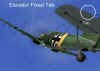
Here is a typical elevator trim tab on a LaGG-3.
The fixed tab and the movable tab both work in the same way. They essentially act as a mini-elevator that is attached to the actual elevator. Moving the elevator changes the shape of the tailplane airfoil, and that results in a change in the lift produced by the tailplane. If the elevator is moved up, the new curvature of the tailplane creates a lifting force that pulls the tail down, as in this figure:
The trim tab works in a similar manner on the elevator itself. The purpose of the tab is to create a lifting force that will take up some or all of the force that the pilot is exerting to displace the elevator. In our example of “up” elevator, the trim tab is situated on the trailing edge of the elevator and is deflected opposite the direction of the elevator. In this case, the tab would be deflected “down” as in the next figure:
The trim tab changes the shape of the elevator trailing edge and forms a small additional airfoil. This small airfoil produces its own lifting force, and this force is directed opposite the main elevator force vector. When the pilot trims the elevator to a “hands off” position, he has moved the trim tab until it creates a lifting force that exactly matches the force that the pilot was making in the first place. The pilot can literally take his hands off the stick, and the elevator will remain in the “up” position because the trim tab lifting force is holding it there.
Inherent in this explanation is the most important thing to remember about trim. The pilot moved the stick to achieve the desired attitude. He then moved the trim system to match the force that he was exerting. He did not trim the nose up…he used his primary flight controls to do that. He used the secondary trim controls to reduce or remove the stick loads that he was feeling.
OK! Having now made that point several times, let’s move on to the stabilizer type of trim.
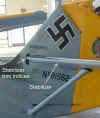
Stabilizer trim. The idea of stabilizer trim was invented before WW2. Some sources say that the Piper Cub was the first plane to use this form of trim. In WW2, the Me-109 used this system as well. The concept is simple. Rather than trim the elevator to remain in a deflected position, the idea was to move the horizontal stabilizer to create the change in tailplane airfoil. This airfoil change resulted in a lifting force that moved the tail up or down just like the elevator trim function did. In the next picture, you can see the Me-109 stabilizer arrangement.

Note where the leading edge of the stabilizer meets the fuselage…see the little opening? That opening allows the leading edge to move up and down. When the pilot moves the trim control in the cockpit, a jackscrew attached to the stabilizer rotates to move the front of the stabilizer up or down. Note also the indices marks…you can see the stabilizer range of movement was much greater in “nose up” (leading edge down), than in “nose down”. The next picture shows the actual linkage that was used to move the stabilizer.
OK! Here is how the trimmable stabilizer worked. Let’s imagine ourselves flying at low speed in level flight. The aircraft is flying at a relatively high AOA. If the stabilizer trim was in the neutral position at this speed, the stabilizer-elevator relationship would look something like this…the stick is held in an aft position and the elevator is “elevated”!

Now we trim the stabilizer to fly “hands off”. This is what it now would look like with the stabilizer trimmed “nose up”.
Note that the leading edge of the stabilizer has moved down and the elevator is now “faired” with the stabilizer (“faired” means “lined up”). In this situation, the tail is generating the same lifting force that the previous tail did. In this configuration, the tail using the trimmable stabilizer is said to generate less drag than the other, thus this second design may be considered to be more aerodynamically efficient than the first.
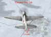
Stabilator trim. When Chuck Yeager broke the sound barrier, he did so after being part of a major discovery…and that was the use of the entire horizontal stabilizer as an “elevator”. Prior to his record flight, horizontal stabilizers had traditionally been one part stabilizer and one part elevator. After Yeager’s history-making flight, aircraft design began to discard the idea of a movable elevator attached to a fixed stabilizer and moved to the concept of a movable one piece tailplane, sometimes known as a “stabilator” (stabilizer + elevator = stabilator). Here is the one-piece F-104 stabilator.

Hand in hand with this development was the introduction of hydraulically powered flight controls. The typical hydraulic flight control system in a fighter operates at a pressure of 3000 pounds per square inch (psi). The same is true of the airliner I fly today. We all know that as speed increases, so do the airloads that try to prevent the flight control surfaces from moving. In WW2 aircraft that had cable controls (in other words, unboosted by any means), these airloads at high speed could prevent the pilot from moving the control stick.
Not so in a hydraulically powered flight control system! 3000psi is enough power to move the flight control surface no matter how fast the airplane is going! So, if the pilot could now move the controls without regard to airspeed loads, did this mean that trim was no longer a consideration?
As it turned out, no. Along with the introduction of the hydraulic control system came the realization that this new system was very difficult to fly. Why? Because the pilot had no “feel” for his controls…and as it so happens, “feel’ is very important. The fix was to build an artificial feel system into the hydraulic flight controls. Now the pilot could once again “feel” the effect of airspeed and G changes. Central to this feature was the trim design that augmented the “feel” system.
But there was one difference. As a rule, this trim system was designed to change the stick “feel”…and since this “feel” was artificial to begin with, the thing to remember about this type of trim is that the system is changing only the artificial forces the pilot feels on his controls…the trim system is not directly moving the flight controls.
Here’s how it worked. When I flew my real life F-4 at slow speed with the trim set for cruise speeds, the stick would feel “heavy”. I would be holding the stick somewhat aft to deflect the stabilator trailing edge “up”. If I then trimmed the nose “up” to relieve this stick “heaviness”, nothing would change with the stabilator. What would change would be the mechanism in the hydraulic flight control system that varied the amount of resistance I felt in the stick. As I trimmed the nose up, the stick would get progressively “lighter” until at some point, I could fly “hands off”. Here, the only thing that actually got trimmed was the stick…the flight control surface remained the same.
OK! Those are the types of tailplane trim set-ups…now, how about aileron trim?
Longitudinal Axis (Roll) Trim
We have seen that elevator trim deals primarily with changes in speed (actually angle of attack, but speed will do for our purposes!). Sometimes, however, we find ourselves having to push the stick right or left to hold the wings level. When we do this, we deflect the ailerons to create lift differences in the two wings.

If we want to relieve the side stick forces that we are having to hold, we would want to trim the ailerons. What might cause us to need to trim the aileron?
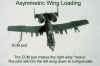
The main reason for trimming the aileron is to balance the lifting qualities of each wing. Why would the two wings need to be balanced? Usually because the wings are supporting different weights…for example, different external stores loads…or different fuel quantities in the wing tanks.
An aileron trim tab is essentially a mini-airfoil attached to the trailing edge of the aileron. This tab airfoil creates a lifting force that will offset the stick force that the pilot is using to hold the aileron out of the faired position. Most aileron trim systems consist of a simple fixed tab or a movable (mechanical or electric powered) tab.
Fixed Tab. In WW2 era fighters, the fixed aileron tab was common and resembled the fixed elevator tab. In these aircraft, the tab deflection was set as the result of factory test flights.
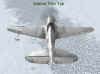
Movable Tab. As aircraft design became more sophisticated, aircraft more complex, and their flight envelopes much wider, the need for something beyond a fixed tab became obvious. This tab functioned exactly like the elevator tab that we have already described. Also note that this LaGG-3 has only one aileron trim tab (left wing), while it has two elevator trim tabs.
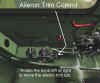
The tab control is a twist knob typically situated on the left side of the cockpit near the throttle and flap controls. Turning this knob raises or lowers the tab relative to the trailing edge of the aileron. This is the aileron trim knob in a P-39.
Aileron trim is probably the least often used trim in a fighter. The third type of trim, rudder trim, is more commonly used, particularly in WW2 era aircraft.
Related Posts:

Related posts:
 Secondary Flight Controls – Part Three: Trim
 Page 2
Secondary Flight Controls – Part Three: Trim Page 4
Secondary Flight Controls – Part Three: Trim Page 5
Secondary Flight Controls – Part Three: Trim Page 6
Secondary Flight Controls – Part Three: Trim
Secondary Flight Controls – Part Three: Trim Page 2
Secondary Flight Controls – Part Three: Trim Page 4
Secondary Flight Controls – Part Three: Trim Page 5
Secondary Flight Controls – Part Three: Trim Page 6
 Secondary Flight Controls – Rudder, Flaps, and Trim
 Page 3
Secondary Flight Controls – Rudder, Flaps, and Trim Page 4
Secondary Flight Controls – Rudder, Flaps, and Trim
Secondary Flight Controls – Rudder, Flaps, and Trim Page 3
Secondary Flight Controls – Rudder, Flaps, and Trim Page 4