Vertical Axis (Yaw) Trim
To some extent, I have discussed rudder trim in the first of these articles on secondary flight controls. I’ll try to hit the major points again in this section.
The main question that comes to mind is “Why do we need rudder trim”? Unlike in the case of aileron trim, there are no asymmetric external stores to worry about. To answer this question, let’s review why rudder trim would be needed in the first place.
And the answer to that is simple…the aircraft is flying “sideways”, meaning in uncoordinated flight! Well, maybe not sideways…but certainly not straight. How would we know this? It’s not exactly like the first two types of trim where we could see the nose not maintaining the desired pitch angle or see the wings rolling away from a level attitude. How would we see the need for trim?
First of all, what’s the problem? The problem is yaw. The nose is cocked off one way or the other. The fuselage is not aligned with the airstream. The aircraft is flying in a bit of a skid. OK…how does the pilot recognize this?
Two ways. In real life, the pilot can “feel” yaw in the “seat of his pants”. Skids produce sideways G forces that pilots can actually feel. The second way is through the observation of certain cockpit instruments. These instruments are the “ball” in the turn and slip indicator, and the heading indicator.
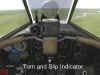
The “ball” in the turn and slip indicator should be centered in the trace. If it is off to one side, then rudder is needed in that direction. So, if the ball is displaced to the right, then right rudder is needed to center the ball. The pilot pushes the right rudder pedal in until the ball centers. This action is referred to as “stepping on the ball”.
The other common way of detecting the need for rudder is to notice that the heading is changing on the heading indicator when the wings are held level. If the heading tends to drift off in one direction, then it’s time to step on a little rudder in the opposite direction to stop this drift.
In either case, the pilot is left holding the rudder. This can get tiring, and so we use rudder trim to take up the force needed to displace the rudder. There are several types of rudder trim. They include vertical fin offset, fixed tab, movable tab, and the control tab.
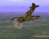
Vertical Fin Offset. It’s not always visible to the casual onlooker, but in some aircraft, the wings and tail surfaces are not always in perfect alignment. Take the vertical stabilizer, for example. It can also be designed with a built-in offset…in this case, to help correct for helical propwash. That’s a fancy term for the airflow that comes off the prop as it makes its way back along the aircraft fuselage.
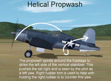
For the typical prop aircraft, this airflow ends up hitting the left side of the vertical stabilizer, causing the aircraft to yaw to the left. The pilot would correct for this with right rudder. The design offset moves the leading edge of the vertical stabilizer slightly to the left…the result is a vertical stabilizer that produces a small amount of right yaw. This right yaw assists the pilot in keeping the plane going straight. The WW2 RAF Hurricane has this feature as you can see in this picture:
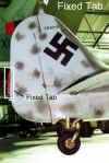
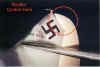
Fixed Tab. Another trim design intended to reduce the pilot’s rudder workload is the fixed tab. As with the aileron and elevator fixed tab, the rudder fixed tab is a small appendage to the trailing edge of the rudder that is preset on the ground based on flight tests. The tab is usually adjusted for cruise airspeed conditions. The Fw-190 used a fixed rudder trim tab as is shown in this next picture.
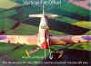
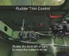
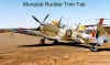
Movable Tab. The rudder movable tab is functionally identical to the elevator and aileron movable tab. It provides a small lifting force that helps reduce pilot rudder input requirements. The rudder trim tab was often controlled by a knob on the left console in the cockpit next to the aileron trim control knob. Here are pictures of the P-39 rudder trim knob and the movable rudder tab on a Spitfire. Note the trim indices located at the base of the rudder knob. These indices told the pilot how much rudder trim was being used.
Control Tab. The rudder control tab is a bit different in that the pilot does not directly control it. Instead, the control tab is mechanically connected to the rudder. When the rudder moves in one direction, the control tab moves in the opposite direction. It is, in effect, an “automatic” form of trim control. The control tab provides the same lifting force to reduce pilot rudder loads and is sometimes known as a Flettner Tab.

Miscellaneous Trim Devices
Additional control features have been designed to reduce pilot workload in keeping his aircraft in balance. Among these are control horns, Frieze ailerons, and differences in incidence angles.
Control Horn. Aircraft designers have come up with many effective techniques to help the pilot fly more efficiently and with less effort. One design feature worth mentioning briefly is the control horn.
The control horn concept can apply to any of the three flight control surfaces but is more commonly seen on the elevator and rudder. As the elevator or rudder surface is deflected away from its faired position, the horn area moves out into the airstream opposite to the main surface. The airstream pushes back on it and, in doing so, produces a force that helps move the entire control surface. The introduction of boosted and hydraulically powered flight controls removed the need for control horns. Here is a picture of an elevator control horn on a Spitfire elevator. The rudder control horn on the Me-109 works in the same manner.

A Frieze aileron is one that when the aileron is moved to the “up” position, a small “lip” moves out into the airstream below the aileron hinge line. This lip creates a small drag force that “pulls” that wing back slightly. The result is a force that helps counter the adverse yaw associated with the opposite wing’s “down” aileron.
The wings, tail, and vertical stabilizer are aligned with the fuselage at certain angles, called incidence angles. We have already described the offset vertical fin. The same concept has been used in prop planes to offset engine torque. Let’s take a typical clockwise rotating engine. In this instance, the engine produces a torque that results in a left rolling tendency. To counter this, the designers give the left wing a slightly greater angle of incidence relative to the fuselage longitudinal axis. This increased angle of attack creates a small increase in lift that helps reduce the torque effect.
Well…enough of this theory and real life stuff! Let’s get into how the simulation attempts to replicate trim devices and pilot techniques.
Related Posts:

Related posts:
 Secondary Flight Controls – Part Three: Trim
 Page 2
Secondary Flight Controls – Part Three: Trim Page 3
Secondary Flight Controls – Part Three: Trim Page 5
Secondary Flight Controls – Part Three: Trim
Secondary Flight Controls – Part Three: Trim Page 2
Secondary Flight Controls – Part Three: Trim Page 3
Secondary Flight Controls – Part Three: Trim Page 5
 Secondary Flight Controls – Rudder, Flaps, and Trim
 Page 2
Secondary Flight Controls – Rudder, Flaps, and Trim Page 4
Secondary Flight Controls – Rudder, Flaps, and Trim Page 5
Secondary Flight Controls – Rudder, Flaps, and Trim
Secondary Flight Controls – Rudder, Flaps, and Trim Page 2
Secondary Flight Controls – Rudder, Flaps, and Trim Page 4
Secondary Flight Controls – Rudder, Flaps, and Trim Page 5