by Andy Bush
Ever lawndarted yourself using padlock in BFM? Who hasn’t, right??!! And what’s to blame? Loss of situational awareness (SA), plain and simple. It seems to me to be a good time to take a brief look at some aspects of situational awareness by pointing out some of the differences in padlock design. In particular, I want to talk about attitude reference systems and how they play a major part in how effective a padlock view is to use.
For this article, I’ll use two of the latest sims out…Flanker 2 and Jane’s USAF. Each has an effective padlock, but they are quite different in function and implementation. The root of this difference lies in how each sim models its attitude indicator system. As you will see, a clear understanding of this design difference is absolutely necessary if you are to effectively use the padlock view. We’ll begin with a brief look at why we have padlock views.
The Reason Why We Have Padlock Views
Everyone knows the forward view is the primary view of any sim. Of all the cockpit views, it’s the one most like what a real pilot sees from his cockpit seat viewpoint. As long as we can keep our target within the field of view of the front canopy, life is good. We chase our target, and we gun him into little bits. This, too, is good. But what if the target somehow manages to fly out of the forward view? This is not good. What do we do now? In the early years, we would selectively choose a different fixed view, such as a side or rear view, to keep the target in sight. Then some clever designer came up with the idea of slewable views. Now we could use the hat switch on our flight stick or a keyboard key to pan the cockpit view to one side or the other. But in either case, we found that, while it was relatively simple to maintain a tally on the target, once we started to maneuver, we had better switch back to forward view or risk the almost certain loss of awareness of our nose position relative to the horizon. The operative word here is horizon…this will be made clear in a minute or two. Of course, once we switch back to check our nose position, we now no longer can see the target. Since keeping the target in sight is strongly recommended, we found ourselves cycling back and forth between the forward view and the other views in a frantic attempt to get our nose to the target before we inadvertently plowed ourselves into the dirt. Some people got pretty good at it, but it was an ugly picture at best.
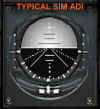
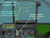
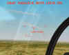
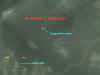
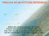
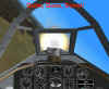
And then, like a white knight coming to the rescue, along came the padlock view. In its simplest form, the padlock is an automatic slewable view that contains additional cues to help the pilot maintain his SA. The following view illustrates one of the early padlock views.

The basic idea is that the padlock view attempts to show what the pilot would see if he were to turn his head to follow the target as it leaves the forward view. One of the most obvious shortcomings of the padlock concept is that there is a physical limit to our field of vision from the cockpit…if the target goes behind our wing or underneath our fuselage, we would lose sight of it in real life, and many sims honor this in their padlock programming. If the target is considered to have gone beyond the physical limits of what a pilot could reasonably see, then the padlock view reverts back to the forward view. Now the pilot is forced to maneuver “in the blind” until he can get back into padlock “lock on” parameters. These parameters vary from sim to sim.
Another major factor in the design of the padlock view is the question of visual acquisition range. Many padlocks will not function unless the sim artificial intelligence (AI) determines that the target is within the visual range of the human eye.
But these factors of cockpit structure limitations and target relative size also affected the fixed and slewable views. So, what was it about the padlock view that made it such a quantum leap forward? The inclusion of some form of attitude or nose indication, that’s what. From the very beginning, most padlock designs have included some cueing device to help the pilot maintain a sense of where his nose was relative to the horizon. It was this additional input of attitude information that set the padlock aside from the other views. Back a few paragraphs, I said that the horizon was going to be something to keep in mind, so let’s do that. Let’s look at attitude reference systems.
Attitude Reference Systems
One way of defining SA may be to say that it is knowing where your pointy end is going! We do that mainly by looking out the window. When we do this, we see some part of the aircraft structure that allows us to sense our nose position, and we also see the ground/sky relationship in the form of a horizon line. But what if we don’t see either? We know this can happen if we are looking out of the canopy into the uninterrupted sky…there’s nothing there! No airplane part, no horizon line. We be in deep kimchi!
Fortunately, avionics designers many moons ago came up with a solution…the attitude directional indicator, or ADI, for short. We know this. The ADI is an integral part of every sim. You see one, you’ve seen them all!
Well, not quite. Here’s where we start to put some meat on the bones of this article. Remember, we began by saying that we were going to use two sims in our discussion…USAF and Flanker 2. The problem is…the US and the Russians have a major difference of opinion when it comes to designing attitude indication systems…and when I say major, I mean major! Here’s what I mean.
The US ADI Design
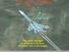
All ADIs have two major components…the aircraft symbol and the horizon reference. All ADI designs have one thing in common…one of these components moves (in other words, responds to pilot control inputs), while the other does not. The next figure shows an actual ADI from an A-10. Please note the miniature aircraft symbol (looks like an elongated “w”. It is superimposed over the horizon line that separates the light (sky) and dark (ground) halves of the ADI ball.

In the US design, the aircraft symbol is fixed and does not move. As the pilot views it, the ADI aircraft’s wings are always level with the cockpit.
The horizon reference is powered by a gyro. This gyro attempts to keep the horizon reference synchronized with the actual horizon. Modern ADIs are unaffected by any maneuver that the aircraft undergoes, and will be a reliable reference under all conditions.
In the US design then, the ADI horizon moves as the aircraft nose position changes. The US pilot looks at the miniature ADI aircraft in the foreground and its relationship to the horizon in the background to determine his attitude. If the US pilot begins a climb, he sees the miniature aircraft in the foreground remain fixed, while the horizon line in the background moves down in the ADI. If he rolls his aircraft, he sees the horizon rotate around the miniature aircraft.

The Russian ADI Design
The Russian ADI design philosophy is 180 degrees opposite the US technique. In the Russian system, the horizon reference is fixed, while the miniature aircraft reference is movable. I need to be clear on this matter. When I say that the Russian horizon is fixed, I mean that the horizon line stays level with the cockpit.

When the Russian pilot makes a control input, he sees the miniature aircraft respond by moving on the ADI. If he begins a climb, he sees the miniature aircraft in the foreground rise above the horizon line which remains fixed in the background. If he rolls his aircraft, he sees the miniature aircraft rolling about the stationary horizon line.

Clearly, these two designs accomplish the same purpose, but their frames of reference are completely opposite each other. It’s not a matter of one design being better than the other…they are both equally effective.
OK!! So what is the point of this? Very simple. We’re talking about padlocks. Specifically, we are talking about how to keep your SA while using the padlock view. The plain and simple truth is that the USAF and Flanker 2 padlocks have an ADI reference imbedded in the view. And you guessed it!! Each is faithful to its particular ADI design. So, folks…you want to fly their padlocks? Great!! But you had better understand the difference in attitude indication design or you may well end up back where we didn’t want to be…in the dirt. Before we go on to the specific padlock systems, let’s take a moment or two to look at what we want to see in a padlock view.
Desired Padlock Components
Automatic Padlock Lock-on. Most padlock designs are available at the press of the appropriate key. Most will be functional if the pilot locks his radar on the target. If the aircraft does not have a radar, the pilot will normally have to designate the target in some other fashion. In any case, having the padlock ready to go without further keyboard activity is a welcome feature.
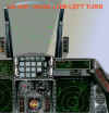
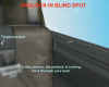
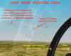
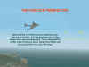
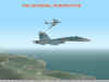
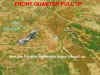
Realistic Visual Limits. In the interest of realism, many of us do not want a padlock to function if the target has gone out of sight, either as a function of excessive range or because of line of sight blockage due to cockpit structure. The following figures show a padlock that has retained its lock even though the target has flown into the attacker’s deep six o’clock. The external view shows the same position as the padlock view.

Nose Position Cues. Many padlocks include a cue to tell the pilot where his nose is. In addition to this important bit of info, the cue also helps orient the pilot to where he is looking…sort of a “I can see the nose is that-a-way, therefore I must be looking this-a-way” technique.


Lift Lines. Many padlocks include symbology known as lift lines. Lift lines are lines drawn on the canopy (typically arrows pointing towards the nose) that are intended to cue the pilot to where his nose is. The lines also have a relationship with the lift vector….more on that in a moment. It may be silly for me to say this…but just in case someone didn’t know…lift lines do not move on your canopy. Think of them as painted on the top and, in some cases, the sides of your canopy. The idea is that when you are looking up and/or to the side and no longer can see any cockpit structure, the lift line will tell you what part of the canopy you are looking out of…and the purpose of the arrow on this line is to indicate the direction of your nose. Lastly, by definition, when you are looking up through your top lift line, you are also looking along your lift vector.
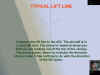
Most lift line designs include one primary line down the top center of the canopy, and secondary lines on the sides of the canopy.


It is important to note that these lift lines move about the monitor screen as the padlock view moves around the canopy. The range of movement of these lines is about 360 degrees, meaning the lift line arrow could be pointing up, down, or to either side as you view your monitor. Regardless of their direction, the lift line arrows serve the primary purpose of increasing your awareness of your nose position.
Most padlocks today do not have a lift vector symbol. Instead what they have is a cue that attempts to direct which way to roll to get the lift vector to overlay the target. That cue is the center lift line. Using this cue is a two step process.
First, the pilot uses the side (or secondary) lift lines to identify that part of the canopy that he is looking out of. Then, the pilot rolls towards the target to bring the center lift line into view. Once the center lift line is over the target, the pilot may begin adding back stick to start his nose moving towards the target.
But we need to understand a very important distinction. The center lift line is always your lift vector…however, if you are trying to turn directly towards the target, the only time that will occur is when the center lift arrow is superimposed over the target.
Here’s another important point to keep in mind. You must also align the lift line with the target’s plane of motion if you expect the lift line to remain centered on the target as you pull back on the stick. If you are not aligned, your pull will result in the lift line moving off the target as you move out of the target’s plane of motion. To correct this, you must add aileron as you pull. That’s the easy part. The hard part is knowing which way to roll. The secret is in the lift line arrow. If the arrow is pointing “up” in your monitor ( from the left side to the top over to the right side), then roll to “pull” the lift line over to the target. However, if the arrow is pointing towards the “down” half of your monitor, then roll to pull the target to the lift line.
Those pilots that have gained the necessary proficiency can derive other benefits from the lift lines. Uppermost of these is the ability to use padlock to fly out of plane BFM maneuvers relative to the target. Using the center lift line, the pilot may then orient his lift vector to fly a lead or lag pursuit course relative to the target. This is exactly how BFM is flown in real life…the pilot rolls to point his lift vector either at the target or away from the target depending on his turning room and closure needs. The “High Six”technique is an example of how a pilot can point his lift vector away from the target.

Attitude Reference. Most padlocks these days include some sort of attitude reference, typically a mini-ADI representation. The importance of this feature is readily apparent. It’s relatively easy to avoid flying into the dirt if you know where the dirt is!
Flight Parameters. Last, but not least, is the addition of flight parameters to the padlock view. A simple altitude and airspeed readout is all that is usually necessary.
Oops…not so fast!! I forgot one other item.
Sim Manual Documentation. All of this is significantly compromised if the sim manual doesn’t cover the padlock view in detail. As we have mentioned, not all padlocks are the same…not by a long shot. It is a major error if sim producers make the assumption that sim pilots understand a sim’s viewing system. No two sims are alike. No two padlocks are alike (unless made by the same company, for example, Jane’s IAF and USAF). Too often these days, sim manuals are chock full of nice-to-know info, and sorely lacking in need-to-know info. Padlock interpretation and operation is way up on my list of need-to-know info.
All right! Let’s get back to the issue at hand. Having laid down these desired components, let’s now go on now to the respective padlock views. In the process, we’ll add a comment or two as to how each view measures up to these criteria.
Jane’s USAF Padlock
Jane’s padlock technique has been around for a number of sims. The USAF design is similar to the IAF padlock. The USAF padlock has some oddities. Please read the following closely.
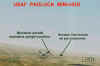
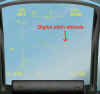
This is the basic padlock view.

The mini-HUD consists of KIAS airspeed (left) and MSL altitude (right) readouts. Centered between them is a miniature airplane symbol. Bracketing the airplane is a horizon line with small legs on each end that point “down” to help identify “up” and “down” relative to the horizon.
A circle will surround the target. This circle will always follow the movement of the target. It will do so regardless of intervening cockpit structure (this means the padlock, once engaged, will always stay on the target regardless of aircraft attitude).
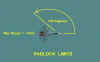
An arrow with a variable line functions as a cueing device to aid the pilot in orienting his lift vector relative to the target. Do not think of this arrow as a lift line. Think of it as a directional indicator. If the arrow is to one side or the other of the mini-HUD, then roll towards the arrow until the line moves to the “straight up” position as seen on your monitor. In this position, your lift vector is now pointed at the target.

The length of the line corresponds to the position of your lift vector to the target. As you roll to orient the arrow line over the target, the arrow line will lengthen as it nears the target. Once the target is pulled to within approximately 45 degrees of the HUD, the line starts to shorten until it disappears as the target enters the HUD area. When the target is ahead of your 3/9 line, the arrow will point in the direction you need to pull. If the target moves behind your 3/9 line towards your six, then funny things happen. The arrow line will become unstable and will settle pointing back in the opposite direction, in other words towards your nose. This is very confusing, and I found that I had to completely disregard the arrow in this situation. Instead I put my attention on the position of the target circle and mini-HUD. I would then continue to turn until I had brought the target back forward of my 3/9 line area where the arrow line would once again reverse back to its “proper” position. For me, the bottom line was to use the arrow line only when I had the target forward of my 3/9 line.
I’ll now discuss the USAF padlock with reference to our desired components.
Automatic Lock-On. Easy to use. You must initially use the radar to lock the target for the padlock to begin its function. From then on, the padlock will retain its lock regardless of whether the radar is locked on or not. When the radar is locked, a square will bracket the target circle and will be absent when the radar is not locked. The padlock will retain its lock regardless of where the target is relative to your aircraft. This will allow you to use the padlock symbology while “looking” through the aircraft structure.
Realistic Visual Limits. Unrealistic. As far as I can determine, there are no limits to padlock range once the initial lock is achieved. I tried extending away from the target, and the padlock retained its lock even when I flew well outside of visual range.
Nose Position Cues. Since the USAF padlock, as it comes out of the box, does not include canopy lift lines, the position of the target with respect to visible cockpit structure will be your best indication of nose position. The mini-HUD position stays centered in the monitor and therefore has no relationship to nose position. Remember, the pointing arrow is a roll cue…it is not a cue to tell you which way your nose is.
Lift Lines. Inadequate. When the target is ahead of your 3/9 line, the arrow line can be used as a lift line cueing device. Roll to align the arrow line “straight up” with the target circle and pull. This is a crude, “g for brains” approach to BFM. Because of the difficulty in determining the position of the lift vector, I do not think the USAF padlock is of much help if you want to maneuver out of plane.
Attitude Reference. The mini-HUD airplane symbol and horizon line make up an effective attitude reference. The top “leg” of the miniature airplane always points “up” as you sit in the cockpit.
The side legs of the miniature airplane always point left and right. The airspeed and altitude numbers are also fixed in their relationship to the cockpit. The mini-HUD is always oriented to you as if you were looking straight ahead at the instrument panel…in other words, the miniature airplane and airspeed/altitude boxes have nothing to do with your attitude to the horizon. To “see” your attitude, you must use the relationship of the mini-HUD horizon line to the miniature airplane. The horizon line will move relative to the miniature airplane. However, there is a big “gotcha” in this symbology. Disregard the horizon bar legs. As you view the monitor, when the airplane is on top of the horizon line, you are nose high…when it is below the line, you are nose low. The legs only tell you if you are inverted or upright…they have nothing to do with whether you are nose high or low.


You can use the mini-HUD as an attitude indicator. Remember our discussion of the US ADI. The miniature airplane is fixed in place while the horizon moves about it. With a little practice, you can fly safely at low altitudes by using the miniature airplane/horizon line reference.One note of caution is warranted. The actual sky/ground horizon line (not the mini-HUD) exhibits strange behavior at times in padlock. This is particularly noticeable in a steep banked, level turn. As you view the monitor, the horizon will at times be “level” (horizontal) with the monitor, even though you are in a steep bank. The only way to describe the effect is to imagine that the aircraft is on its side in a steep bank, but somehow the pilot is still sitting upright relative to the horizon and is looking out the 3 or 9 o’clock position. This is a weird sensation. In this situation, the horizon must be totally ignored, and the mini-HUD must be the sole reference for aircraft attitude. This effect is so disconcerting that I think it largely negates the value of the USAF padlock. The next three figures show this clearly. As the target flies from the pilot’s forward quarter (approx 1:30 o’clock position) past the 9 o’clock to his aft quarter (approx 4:30 o’clock position), the horizon does a complete 180-degree flip-flop. Needless to say, this can bamboozle even the most experienced pilot!!


One final note regarding attitude control in USAF. Have your HUD at the brightest possible color choice. Realize that your choice will depend upon the color of the background terrain. Lastly, roll response under g is slow in USAF…therefore, for quickest roll response, unload to one g or less before you begin the aileron input.
Flight Parameters. Excellent. In addition to airspeed and altitude, the padlock mini-HUD also includes armament remaining, thrust setting, g load, and waypoint info.

Manual Documentation. Extremely poor. I obtained all of the above info through trial and error. None of the padlock functions were explained or described in the manual.
Overall, I consider the USAF padlock (as it comes out of the box) to be of marginal value as a maneuvering tool. The opportunity for disorientation is too great to risk its use when the target is behind your 3/9 line. Thank the stars above that USAF has an excellent Player-To-Target view…it will be what I use when I want to turn and burn with the bad guys.
After Market Improvements
There is an add-on lift line file that improves your ability to use the view. You may download it fromhttp://www.wargamer.com/janeshangar/usaf/indexusafcontest.asp. Find the file under “Plane Art”.

This file adds arrow lines to the canopy that may be used to orient the lift vector to the target. The arrows point to the nose of the aircraft. To orient your lift vector at the target, roll to place the center arrow over the target. When you do this, you will notice that the pointing arrow has moved into alignment with the lift line.
Flanker 2 Padlock
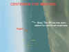
The Flanker 2 padlock is very similar to the original Flanker view. The following describes the basic padlock view. The target is highlighted by a crosshairs symbol centered on middle of the target. This symbol remains in the upright or “+” position regardless of target orientation.
The target itself is not centered in the screen but moves about as a function of the pilot’s look angle…as the nose of the aircraft moves further away from the target, the target moves closer to the opposite side of the monitor screen. For example, if the pilot pulls his nose up above the target, the target will move “down” on the screen, and, again, if the pilot turns away from the target (or the target turns away from him), the target will move towards the opposite side of the screen.
A mini-HUD is placed on the screen. When a missile is selected as the armament, this mini-HUD consists of airspeed and altitude parameters as well as a horizon and miniature aircraft reference.

In a guns only configuration, the horizon and aircraft symbology are absent.

The horizon line is a solid line with the airspeed above the left side and the altitude above the right. The miniature aircraft consists of two parts. The center of the symbol is an upright crosshairs (similar to the symbol bracketing the target). This symbol remains upright in the monitor screen regardless of aircraft orientation. This symbol represents the nose of the pilot’s aircraft, and as such moves “up and down” relative to the fixed horizon line to show the pilot’s pitch attitude relative to the horizon. Attached to this symbol are three lines that may be thought of as the rudder and left and right wings. The wings have a small peg line underneath each wing to represent the bottom of the aircraft. These wing and rudder lines rotate about the crosshairs symbol as the aircraft changes its bank angle. Therefore, the mini-HUD displays aircraft attitude as the combination of two separate symbols. The crosshairs position relative to the fixed horizon line shows your pitch angle, and the wing/rudder line position relative to the fixed horizon show your bank angle. Put the two together, and you get the whole picture.
The mini-HUD moves about the screen to show relative nose position. For example, a mini-HUD at the lower left hand corner of the screen indicates that the nose of the aircraft is down and to the left of the pilot’s view. This situation means the pilot is looking up and right.

The mini-HUD flight data and crosshairs orientation is always level with the monitor, in other words to you, the pilot. As such, this mini-HUD general orientation is of no value in determining aircraft attitude.
When visible (in missile mode), the horizon line and aircraft symbol may be used as an ADI. Remember our discussion of the Russian ADI methodology. The padlock attitude reference functions the same as the cockpit ADI. The horizon line is fixed in place, and the miniature aircraft symbol moves about it as the aircraft is maneuvered. A digital readout of pitch angle is included on the right side of the horizon line.
The padlock view is only available when the target is within predetermined visible range and aspect limits. Maximum padlock range is approximately 12 km. The aspect limits are derived from the Su-27 cockpit design restrictions to visibility. The target may not be obstructed by aircraft structure, and the target position must not get further aft than your 8 or 4 o’clock position as you look out of your canopy. Using your wings as a reference, this means you have a “blind” area of 60 degrees either side of your six o’clock. If the target flies into this area, the padlock will break lock and return to the forward view.
Now let’s look at how the Flanker 2 padlock stacks up against our desired components.
Automatic Lock-On. The padlock view will only be available if a sensor (IR or radar) is locked on to the target to begin with. If the padlock is broken because the target exceeded the range or visibility restrictions, then it will have to be brought back into lock on parameters before the padlock will again function.
Realistic Visual Limits. Excellent. If you allow the target to exceed the maximum allowable range or aspect limits (about 12km and +/- 120 degrees off the nose), you will get a padlock “break lock” in about 5 seconds. When this happens, the padlock view will revert to the forward view. As a matter of “realism,” this is not well modeled. In real life, if the target flies into the six o’clock blind area, the last thing the pilot does is to look forward to the HUD area. Instead, the pilot usually will continue to look to the area where the target was last at while he maneuvers to bring the target back into view.

Nose Position Cues. Adequate. The position of the mini-HUD is a useful indicator of nose position, particularly when the target is behind the 3/9 line. The mini-HUD can be disorienting when the target moves towards your six o’clock. In this situation, the mini-HUD often moves from side to side as if it cannot make up its mind where to be. In times like this, a brief period of g (back stick) is often all that is necessary to move the target far enough away from the six o’clock to settle the mini-HUD down.

Another aspect of this padlock’s ability to display nose position arises when we look at a target that is moving from our forward quarter (1 – 2 o’clock) to our aft quarter (4 – 5 o’clock). In this situation, the padlock can “flip-flop” as it attempts to settle down. The following views show this. The first figure shows you in a hard right hand turn, level with the horizon. The target is out of view at your high twelve. The next set of views show the padlock flip-flopping the view until in the fourth figure, the view stabilizes with you in the proper aspect.


Lift Lines. As it comes out of the box, the Flanker 2 padlock view does not have a lift line. The top leg of the mini-HUD miniature airplane (the rudder) indicates the relationship of the lift vector to the horizon, but it cannot be used as a reference relative to the target. This means you cannot roll to aim the rudder at the target as a means of positioning the lift vector. In the padlock view, the rudder line and the target are not interrelated. They are two separate pilot cues that must be used in concert to solve the lift vector orientation problem. The pilot does this by rolling his aircraft until the mini-HUD moves to the center of the screen. In that position (and only that position) is the pilot’s lift vector is pointed at the target. As is the case in USAF with the arrow line, the Flanker 2 mini-HUD position is only a directional indicator of which way to roll to bring the mini-HUD to the center or “straight up” position.
An important note of clarification is needed here. The mini-HUD provides two types of info. First, it is used to direct you on which way to roll to orient your lift vector…this is done by bringing the mini-HUD to the center of the view. For this purpose of centering the mini-HUD, you are not looking at your attitude relative to the horizon. Specifically, you are not using the mini-HUD’s miniature airplane rudder to orient your direction of roll…instead, you are only looking at the mini-HUD’s position in the monitor screen relative to the target. Secondly, the mini-HUD is used as an ADI to keep yourself oriented relative to the horizon. For this purpose, the mini-HUD is viewed without respect to the target.
Attitude Reference. Good, but ya got to know what you’re looking at!! There was a reason why I discussed the differences between US and Russian ADIs, and now the truth can be told! In the F2 padlock, you must keep in mind that the horizon line remains fixed in place while the miniature airplane moves with respect to it as you maneuver above or below the horizon line. That’s easy enough. But you must also remember that the horizon line does not follow the actual horizon…instead, the mini-HUD horizon line stays level with the monitor…as it would appear if you were to look at the instrument panel ADI.
What is the significance of this? Major…that’s what. You must view the mini-HUD as a “stand alone” attitude reference. Under no circumstances should you attempt to fly the mini-HUD while also referring to the background horizon. To do so invites disaster…there is no correlation between the two.
The mini-HUD is an effective attitude indicator. Because of the airspeed and altitude readout accompanying the mini-ADI, you can safely fly at minimum altitude using just this reference. In comparison to USAF, I think the Flanker mini-HUD attitude indicator is much easier to use. The Flanker movable aircraft is considerably larger than its USAF counterpart, and its relationship to the fixed horizon line is easier to quickly interpret.
The best advice for how to view the attitude info available in the padlock view is to break the whole view down into its individual parts. There are three main parts…the background horizon, the mini-HUD, and the target. Of these, the background is of least value. My advice is to essentially ignore it. Instead, concentrate on the relative positions of the target and mini-HUD on the screen. This will clue you in to where your nose is. Next, you want to crosscheck the mini-HUD flight parameters and nose position to make sure you aren’t on a one way trip into the dirt.
Having done that, then you can move on to the most important part of the padlock view…how to get out of it!! You do that by getting the target on to your lift line. Once there, you pull back on the stick to bring the target to your nose. As mentioned before this is a “g for brains” technique and is not good BFM. But, if the turning room is adequate, it will “work”.
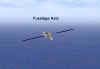
Flanker 2 does not have an external Player To Target view similar to USAF. You may get similar results, however, by using the Air Combat view (F5) in conjunction with the keypad 2, 4, 6, and 8 keys to view your aircraft relative to the target. The external view is shown next with its respective padlock view.
Lastly, as in USAF, select the most visible HUD color depending on background terrain color. Your choices are limited…I’ve had the best luck with the bright ‘yellow” color for most situations.
Flight parameters. Adequate in missile mode…very poor in guns mode. The absence of the mini-HUD in guns mode is a mystery to me. Some of the other info that other sim padlocks provide would be nice…but not necessary. My workaround for this is to fly in missile mode to be able to have the entire mini-HUD for use. When I want to use the gun, all it takes is a quick peck at the C key (or the programmed button on my stick) to get me the gun display.
Sim Manual Documentation. Very poor. The manual says little about how to get into padlock or how to use it. If you have the original Flanker sim manual, you can find additional padlock information in it.
After Market Improvements
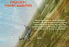
As with USAF, there is an after market add-on file that places lift lines on the canopy. These point towards the nose as in other sim lift lines. Once again, please keep in mind that these lines are better used as roll cues to help you orient your lift vector rather than as an aid to identifying nose position.


A file is available for those with 3dfx video cards that may improve the graphics of this lift line. Get this file from: http://www.papadoc.net
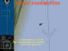
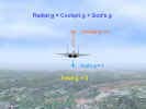
You can see the add-on lift line in the following figure. You want to roll to place this lift line over the target. In this situation, you would roll slightly right. The accompanying external view makes this more evident.

So What’s the Point??
- Know what your attitude indication system is telling you.
- Know how that attitude reference system is portrayed in the padlock view.
- Know how the padlock view attempts to show your attitude relative to the world, i.e. the background horizon.
- Know how the padlock view attempts to show your attitude relative to the target, i.e. your nose position.
- Know your padlock system lock-on, range, and visibility limitations.
- With all of this in mind, kill the bandit.
One final note. Because of the absence of any substantial info on these two padlock views, most of my observations made in this article are just that…my observations. I may have made mistakes. If so, please contact me. I’ll revise this text and repost it. My objective is to give you the best info I can.
Related posts:
 Air Combat Basics: The Scissors Maneuver Page 2
Air Combat Basics: The Scissors Maneuver Page 3
Air Combat Basics: The Scissors Maneuver Page 4
Air Combat Basics: The Scissors Maneuver Page 2
Air Combat Basics: The Scissors Maneuver Page 3
Air Combat Basics: The Scissors Maneuver Page 4
 Boom and Zoom Tactics, Part Three
 It’s All a Matter of Perspective – Part Three
 It’s All a Matter of Perspective – Part Two
 Lt. Col. Andy Bush (USAF, Ret) The A-10 in the 1980s
 Secondary Flight Controls – Flaps Page 3