Stadiametric ranging
Stadiametric ranging uses the relationship of small angles and the arcs they subtend over a given distance. Whew!! I hope you are still with me!! Here is the basic idea.
We all are familiar with how we use clock code to define a position around our aircraft. Each one hour of the clock represents an angle of 30 degrees. We can use angles to estimate range, as well as position. We begin by focusing on a very small angle…one degree. I ’ll now draw a figure that shows how this small angle can be used to compute range. The point of origin for this angle will be our gunsight, and the lines of the angle will be projected along the sight line. Sometimes a picture is easier to understand.
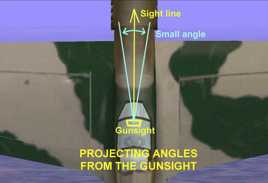
Now, we go to the math part. The distance between the two lines of the angle is known as the arc that the angle subtends. Fighter pilot instructors will say it this way; “The angle ‘x’ subtends an arc of ‘y’ feet at a distance of ‘z’ feet.” Notice the unit of measurement for distance is feet. The unit of measurement for angles is NOT degrees…it is a value known as a ‘mil.’ There are about 17 mils in one degree…so a mil is just a very small angle. This is the definition of a mil:
A mil is an angle that subtends one foot at 1000 feet range. The arc size versus range relationship is linear, therefore, one mil = one foot at 1000 feet, two feet at 2000 feet range, and so on. Similarly, if one mil = one foot at 1000 feet, then 10 mils equals 10 feet at 1000 feet range, 20 feet at 2000 feet range and so on.

Let’s show a practical example of this concept. Go out to your car and then pace off exactly 50 feet and mark that spot. Now, get a piece of glass and look through it at your car. Draw a line on the glass equal to how long your car appears. Next, draw a circle on that piece of glass with a diameter equal to that line. You now have a tool to find out how far 50 feet is using your car as a reference. Just walk towards your car looking through the glass. When the car length matches the diameter of the circle, you are at 50 feet!!
Now we take this idea and apply it to a gunsight. Let’s draw a circle on a piece of glass and say its diameter is a certain number of mils wide. If we were to hold that circle up in front of our eye and look through it, then the circle could be used to show what a certain distance looks like at a given range. For example, if we said that the circle had a diameter of 50 mils, then the circle would span a distance of 50 feet at 1000 feet range.
You know where I’m going with this…right?!! Now, we’ll think of that circle as our gunsight reticle. We know the mil value of the gunsight reticle…50 mils in this example. The two remaining variables are range and arc distance. Let’s change the name ‘arc distance’ to ‘wingspan.. We now have a simple mathematical situation where we can solve the problem of determining target range. Here’s how. Pick a target…say a Su-27. Its wingspan is a known value…approximately 50 feet.
Let’s put ourselves at the Flanker’s six and compare its wingspan to our 50 mil reticle. Picture in your mind the wingtips just touching the edges of the reticle. The range computation is “The 50 foot wingspan is 50 mils in size…therefore the range is 1000 feet.” Now, let’s pull the power back and increase our distance behind the Flanker. When we look at the Flanker in the reticle now, its wingspan looks to be about one fourth of the reticle diameter, or about 12 mils. What is the new range? Divide the observed wingspan size in mils into the known wingspan size in feet…forget about the decimal points!! 12 into 50 equals about 4…so the range is about 4000 feet. The next figure explains the process.

Some might ask why am I going through all this hoopla. The answer is simple. Effective use of the gun requires a pilot to estimate range quickly and correctly. Gunsight reticle and funnel displays are made to be a certain size to help the pilot accomplish this.
Related Posts:

Related posts:
 Air To Air Gunnery – Theory and Application, Part Three Page 10
Air To Air Gunnery – Theory and Application, Part Three Page 12
Air To Air Gunnery – Theory and Application, Part Three Page 13
Air To Air Gunnery – Theory and Application, Part Three Page 16
Air To Air Gunnery – Theory and Application, Part Three Page 17
Air To Air Gunnery – Theory and Application, Part Three Page 18
Air To Air Gunnery – Theory and Application, Part Three Page 5
Air To Air Gunnery – Theory and Application, Part Three Page 10
Air To Air Gunnery – Theory and Application, Part Three Page 12
Air To Air Gunnery – Theory and Application, Part Three Page 13
Air To Air Gunnery – Theory and Application, Part Three Page 16
Air To Air Gunnery – Theory and Application, Part Three Page 17
Air To Air Gunnery – Theory and Application, Part Three Page 18
Air To Air Gunnery – Theory and Application, Part Three Page 5
 Air To Air Gunnery – Theory and Application, Part Two page 4