We are now at the heart of the AOP matter. If those math wizards can compute the IPP at roll out, then they can just as easily compute the angle between the target and the flight path (AOP). The problem in the past was always how to know where the flight path was on the combining glass (the term for a HUD in the old days). In the F-4, we used an approximation. We estimated that the flight path from our point of view in the cockpit was at or near the top of the combining glass. In the roll in, we pulled the top of the combining glass to a point past the target and then relaxed g and rolled out. This would assure that our nose was aimed long of the target. Then, we would set the desired IPP and, presto, we would have our roll out picture!!
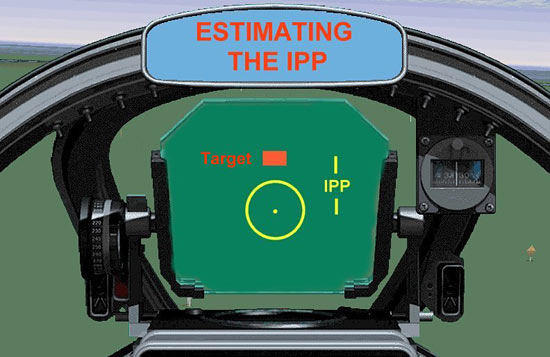
Fig 14 – Estimating The IPP
It’s a bit easier today with our modern HUDs. We have the velocity vector to aim long…no more guessing or rough approximations. On the other hand, we still have the task of getting the velocity vector pointed at the correct spot long of the target. So, what do we do?
Well, for one thing, we could try to position the velocity vector at the mil value that the math guys gave us (similar to the IPP technique), but there is a simpler way…a ‘no brainer’ technique for fighter pilots. Here’s how it works:
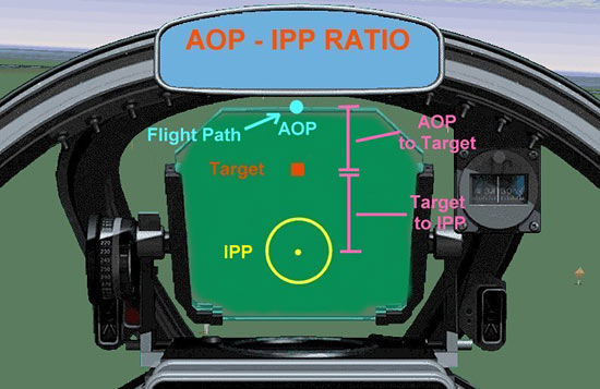
Fig 15 – The AOP/IPP Ratio
We start with the total mil value from the AOP to the IPP. Then, we break that number down into its two parts…AOP to target, and target to IPP. Next, we round those numbers off (to keep things simple), and make a ratio out of them. For example, we may have a total mil depression value of 150 mils with the AOP to target value as 70 mils, and the target to IPP value as 80 mils. Our resulting ratio is 70 over 80, which is pretty close to 50:50 or ‘half and half.’ The technique is to roll out with the nose long and as you roll wings level, you raise or lower your pitch to get the target about halfway between the velocity vector and the IPP. The point of emphasis in this technique is the positioning of the target between the flight path and the pipper in a predetermined ratio. Do this, and by definition, you have set the AOP properly.
Whew!! Well, Bubba, if you are still with me, you just got your aircraft aimed at the AOP!! Congratulations for hanging in there! Let’s finish this section with a few words about tracking the target.
Tracking The Target
Tracking the target consists of the pilot checking his dive angle, setting his throttle to hold his desired release speed, and then comparing how the pipper moves towards the target as he descends on his dive angle. Tracking begins at the roll out point…that’s why we also refer to it as the track point. If the pilot were to fly a perfect pass, the pipper would march right up to the target and reach it just as he reached his desired release altitude.
So much for the perfect pass…but perfect passes are the exception rather than the rule. If this is the case, then what do we do when we ‘track the target?’ The answer is ‘error analysis’! “Ah yes”, you say, “You discussed that in Part One.”
In fact, I did mention it! And now is the time to bring it into the picture. You will recall I said there are two kinds of errors…flight path errors and release point errors. The ‘tracking the target’ phase of the dive bomb pass is where you look through the HUD or combining glass, identify any existing errors, and then correct them as much as possible. I say ‘as much as possible’ because some errors are so large that you will only be able to reduce rather than eliminate their effect.
Let’s start off with flight path errors since they are the easiest to recognize and the easiest to correct. Here’s another look at a flight path error situation.

Fig 16 – Flight Path Error
This is the most important thing to know about flight path errors. They are right/left errors, so obviously you must correct your flight path one way or the other. Do not, under the pain of a thousand lashes, even think of trying to correct your flight path by using the pipper as a reference. Remember, the pipper is depressed below your flight path. If you try to correct your flight path by using the pipper as a reference, you will fall victim to what is referred to as the ‘pendulum effect,’ and the result is that you will most likely weave back and forth trying to get yourself lined up. Instead, you want to use the flight path marker (tadpole, velocity vector, top of the combining glass, etc). You are making a right/ left correction to the AOP, not a short/long correction. Do this by first noting how much lateral correction you need, then bank in the desired direction to move the flight path marker the same amount to the right or left of the original AOP. Next, roll wings level and check to see if you are now on the proper flight path, meaning your projected flight path will run through the target. If not, repeat the process.
Flight path errors are relatively easy to correct…not so with release point errors. Recalling Part One, we remember that release point errors result in misses that are short or long of the target. And we remember that release point errors are the result of dive angle, airspeed, altitude, and incorrect AOP errors. Let’s try to visualize these errors.
We begin at the roll out point. As we fly down the final, we happily see that our projected flight path runs right through the target. “No stinking flight path errors for me!,” you say to yourself. But something is amiss! A check of your dive angle shows that you are a couple of degrees steep. A glance at your airspeed indicator and you realize you have forgotten to pull the throttle back…you are too fast! You look at your IPP and realize it is too close to the target. A quick look at your altimeter and you realize you only have another second or two to come up with a correction. What do you do??
Well, it’s too late to call upon divine intervention. You gotta remember those error analysis charts we saw in Part One. You quickly realize your dive angle, airspeed, and IPP errors will all result in the bomb going long, so you decide that the only recourse you have is to pickle the bomb off early, in other words above the planned release altitude. This will offset the long errors and hopefully save you a round of drinks at the bar later on! This is the basic idea of how to correct for release point errors…recognize what the error is and its effect, and then implement a corrective action to minimize the error.
This was said earlier, and I’ll say it again. As a rule, never change the 6/12 o’clock position of the AOP. You may move the AOP right or left to adjust your flight path, but avoid changing its position long of the target. This mucks up your dive angle and makes the other errors that much harder to correct. If your AOP is incorrect, then leave it alone and make a release point adjustment to correct the problem.
That raises the question of what are these corrections? Since we’ve decided that we are not going to alter our AOP (and therefore, dive angle), we are left with release altitude and release airspeed to play with. Most often we end up making an adjustment in our release altitude; airspeed changes are tough to make in the few seconds of tracking time that we have. So, we pickle slightly early or late, as required, to essentially shorten or lengthen the bomb range to correct for our error(s).
Piece of cake, right!! No, I didn’t think you would think so. This dive bombing thing is a very complicated skill to master. It makes BFM look like child’s play. I’ll finish this article by taking you through an imaginary dive bomb pass.
Related Posts:

Related posts:
 Air To Ground Basics – Bombing Page 4
Air To Ground Basics – Bombing Page 5
Air To Ground Basics – Bombing Page 6
Air To Ground Basics – Bombing Page 7
Air To Ground Basics – Bombing Page 8
Air To Ground Basics – Bombing Page 4
Air To Ground Basics – Bombing Page 5
Air To Ground Basics – Bombing Page 6
Air To Ground Basics – Bombing Page 7
Air To Ground Basics – Bombing Page 8
 Air To Ground Basics – Bombing, Part Two Page 2
Air To Ground Basics – Bombing, Part Two Page 5
Air To Ground Basics – Bombing, Part Two Page 8
Air To Ground Basics – Bombing, Part Two Page 2
Air To Ground Basics – Bombing, Part Two Page 5
Air To Ground Basics – Bombing, Part Two Page 8