What are the typical types of flaps?
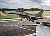
Flaps come in two basic forms…leading edge (LE) and trailing edge (TE) devices. Most fighters with LE flaps are modern day jets. The F-104 is a good example.
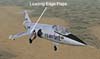
Don’t confuse a LE flap with other types of LE devices that open up or extend. Think of the LE flap as part of the wing that is hinged to bend up and down, not open up or extend.
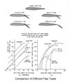
Trailing edge flaps come in a variety of types…plain, split, slotted, and Fowler. You may see any of these in our sims.

The plain flap is simply a section of the trailing edge that is hinged to bend down. The TE flap of the F-100 is a plain flap.

The split flap is different from the plain flap in that the flap consists of a plate that is lowered from the TE bottom section of the wing. The upper section of the wing remains unchanged. Here is an example of a split flap on an A-4.

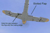
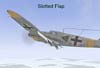
Next is the slotted flap, so named because of the space that is formed when the flap is lowered. The slotted flap, unlike the plain flap, has a gap between itself and the trailing edge that allows the airstream to flow through. Note that the chords of the plain and slotted flap are approximately the same. Here is the slotted flap on a Me-109. You can see the gap (the slot) between the flap and the trailing edge. The slotted flap is generally more efficient than a plain flap.
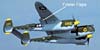
The Fowler Flap takes the slotted flap principle further into the area of advanced aerodynamics. Not only does the flap extend down into the airstream, but it also extends backwards as well. In doing so, the Fowler flap extends the chord line and consequently the wing area. This additional area along with the slot effects results in the Fowler-type flap producing the greatest change in lift. The P-38 used TE Fowler flaps.
The next diagram shows the differences in Cl that result from the different types of flap design.
What is a slat?
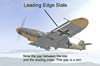
A slat is part of the LE of a wing that is designed to move forward and back. In the back position, the slat is often faired completely into the wing. In the forward position, the slat “opens up” and moves forward creating a space between the slat and the LE. Now comes the confusing part! This space between the LE and the slat is called a “slot”. Earlier in our slotted and Fowler flap discussion, we saw the same thing happening when a space was created between the flap and the TE. The “slot” is the opening where the airstream flows through as it makes its way rearward.

What does a slat do?
The movement of this airstream is very important to both the LE slat and the TE slotted and fowler flaps. What happens is that the force of the oncoming air forces the airstream through the relatively narrow slot opening. In doing so, the airstream is accelerated to a higher speed. It is this greater speed that accounts for the improvement in the amount of lift. In the days before WW2, many thought the primary purpose of the slot opening was to “smooth” the airflow over the wing (or flap). It wasn’t until several years later that the actual aerodynamic advantages of the increased speed of the airstream was fully understood and appreciated. This next diagram shows the additional lift produced by the slat in conjunction with TE flaps.

Slats may be extended in one of two ways. The earliest method was to hinge the slat so that the normal force of the oncoming airstream would push the slat back and hold it in place. If the angle of attack of the wing were to be increased past a certain value, then the oncoming airstream came from a different angle…one that creates aerodynamic forces that cause the slat to move forward. Modern slats are typically electrically or hydraulically powered and controlled automatically by a flight computer or by pilot commands.
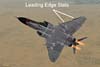
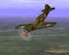
Here are the slats in a Me-109. These opened as a function of angle of attack, NOT airspeed.
The LE slat of a F-4E operated hydraulically and was normally controlled by a computer.
What is a slot and what does it do?
Up until now, we have referred to a slot as the space between a flap or slat. That’s still true! But, we also have a form of high lift device known as a “slot” as well. In this case, the slot is still an opening in the wing…but now, it’s a permanent one…one deliberately built into the wing to create the increase in airstream speed that we have already described. This type of device is called the “fixed slot”. Here, in the wing of the WW2 rocket fighter, the Me-163, we can see the slot that extends along the outboard portion of the forward section of the wing.

Here is a diagram that shows the typical effect on Cl of the fixed slot.

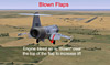
Boundary Layer Control Devices . Before we go, one quick mention of another type of high lift device that we may see. Remember how we talked about the advantages of a slot increasing the velocity of the airstream in a slotted or fowler flap…and how this made the flap more effective. We can achieve that increased lift another way…by forcing air over a TE flap to delay its separation and resultant loss of lift. High-pressure air is taken directly from the jet engine and routed to the TE flap area where it is expelled along the upper surface of the flap. This system is designed to improve the layer of air along the flap and help it “stick” to the flap (if the airflow separates from the flap, lift is decreased or lost completely). This layer of air is called the “boundary layer”, and the method of improving the airflow over this layer is called “boundary layer control (BLC)”. Both the F-104 and F-4 both use the BLC technique. You may also see the term “blown flaps” used in the place of “BLC”.
Related Posts:
Related posts:
 Secondary Flight Controls – Flaps
 Page 3
Secondary Flight Controls – Flaps Page 4
Secondary Flight Controls – Flaps Page 5
Secondary Flight Controls – Flaps
Secondary Flight Controls – Flaps Page 3
Secondary Flight Controls – Flaps Page 4
Secondary Flight Controls – Flaps Page 5
 Secondary Flight Controls – Rudder, Flaps, and Trim
 Page 4
Secondary Flight Controls – Rudder, Flaps, and Trim Page 6
Secondary Flight Controls – Rudder, Flaps, and Trim Page 7
Secondary Flight Controls – Rudder, Flaps, and Trim
Secondary Flight Controls – Rudder, Flaps, and Trim Page 4
Secondary Flight Controls – Rudder, Flaps, and Trim Page 6
Secondary Flight Controls – Rudder, Flaps, and Trim Page 7