Above 1500′ (1170′ radar altitude) I ease the nose down a bit to accelerate and note the red bar on the airspeed indicator indicating the maximum flap speed in our current configuration (Flaps 1).

I retract the flaps and maintain runway heading until passing 8 DME then enter the right turn toward the TOU VOR while reducing the power to the CL detent for the climb.


Center gives me an unrestricted climb to FL240 so I relinquish control to the autopilot, set 300 knots in the airspeed and let her climb. Through FL180 the altimeter setting box flashes in the lower corner of the EADI to remind me to set the altimeter to standard (29.92) on the FCU.
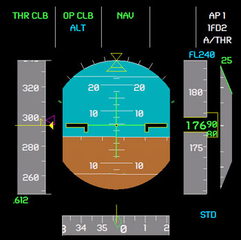
Level off at FL240 is accomplished smoothly and I can see the flight planned route extending in front of us on the navigation display.

Probably one of the most controversial aspects of the Airbus design philosophy is the implementation of the flight regime limits which the pilot cannot override. The Airbus doctrine basically states that preventing a pilot from placing an aircraft into a dangerous attitude is far better (and more proactive) than giving him the extra margin of total aircraft control to extricate himself from a situation he should have never gotten into in the first place. We won’t debate that in this part of the series, but I did want to explore the boundaries that PSS coded into their offering.
Rolling the aircraft into a hard left bank and keeping the control stick firmly against the left stop I wait to see what will happen. Just as in real life the aircraft banks to 67 degrees of bank and will go no further.

There was a bit of a pitch oscillation and the VSI started a huge rate downward and to tell you the truth I don’t know enough about the fly-by-wire design of the Airbus to know if this is normal. Reading the PSS manual it states: “Forward-aft stick deflection controls aircraft G load. Neutral stick position commands load of 1G resulting in level flight or constant vertical speed.” I interpret that to mean that if I want to maintain altitude in a 67 degree bank I will have to use significant G-load (greater than 2G) via stick input and that the flight computer doesn’t automatically input this value to maintain a level turn. Once I did input the required rear stick displacement to hold level flight the aircraft lost speed very rapidly and trended toward a stall despite the fact that the auto-throttles commanded maximum power in an attempt to regain airspeed lost during the maneuver. I would think that at 24,000′ the A320 should have no problem maintaining a 67 degree bank, constant altitude turn without stalling even though it would obviously be an extremely uncomfortable maneuver for passengers.
Rolling back to the right I rolled again into the maximum bank angle (67 degrees) then released the stick to neutral and observed the proper response; the flight computers commanded a return to the maximum neutral stick bank angle of about 33 degrees.
With automatic trim the Airbus should maintain pitch and bank indefinitely until the pilot commands another attitude. For the most part the PSS Airbus replicates this feature of the fly-by-wire system, but there is a bit of gradual release of the bank angle over time. I measured a reduction in bank angle from 30 degrees to 20 degrees over 2 minutes and a further reduction down to about 5 degrees of bank after 5 minutes. Working within the limitations of Flight Simulator I feel these are reasonable allowances since rarely will you put an aircraft into a steady state bank lasting any more than a minute or so.
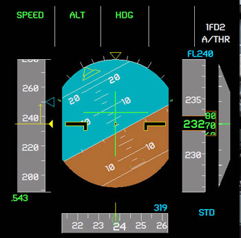
With the roll limits tested I moved on to the pitch testing (much to the discomfort of my 10 passengers). With the auto-throttles set to maintain 250 knots I entered a moderate rate pitch to the maximum allowed by the Airbus envelope protection of 30 degrees nose up pitch. PSS nailed this limitation right on as well and with neutral stick the aircraft maintained 30 degrees nose up as the airspeed started to decay.


They may be hard to see, but the flight envelope attitude limits are on the EADI and are represented by small green tick marks next to the pitch ladder and the sides of the ADI for roll. As speed decayed the airspeed tape started to move into the Alpha Protection zone (orange hash marks) at which the Alpha Floor modeling kicks in. Designed to prevent the pilot from stalling the aircraft the Alpha Floor will command maximum engine thrust while simultaneously limiting the pitch angle such that the aircraft will not stall. This means full aft deflection of the stick may still result in the nose pitching down to prevent exceeding the critical angle of attack. Don’t be fooled into thinking the aircraft is “giving away” performance however, the flight computers are calculating the absolute maximum amount of performance available without losing control of the aircraft.

Related Posts:

Related posts:
 Boeing vs. Airbus – Part 3 Phoenix Simulation Software Airbus A320
 Page 10
Boeing vs. Airbus – Part 3 Phoenix Simulation Software Airbus A320 Page 2
Boeing vs. Airbus – Part 3 Phoenix Simulation Software Airbus A320 Page 3
Boeing vs. Airbus – Part 3 Phoenix Simulation Software Airbus A320 Page 5
Boeing vs. Airbus – Part 3 Phoenix Simulation Software Airbus A320 Page 7
Boeing vs. Airbus – Part 3 Phoenix Simulation Software Airbus A320 Page 8
Boeing vs. Airbus – Part 3 Phoenix Simulation Software Airbus A320 Page 9
Boeing vs. Airbus – Part 3 Phoenix Simulation Software Airbus A320
Boeing vs. Airbus – Part 3 Phoenix Simulation Software Airbus A320 Page 10
Boeing vs. Airbus – Part 3 Phoenix Simulation Software Airbus A320 Page 2
Boeing vs. Airbus – Part 3 Phoenix Simulation Software Airbus A320 Page 3
Boeing vs. Airbus – Part 3 Phoenix Simulation Software Airbus A320 Page 5
Boeing vs. Airbus – Part 3 Phoenix Simulation Software Airbus A320 Page 7
Boeing vs. Airbus – Part 3 Phoenix Simulation Software Airbus A320 Page 8
Boeing vs. Airbus – Part 3 Phoenix Simulation Software Airbus A320 Page 9