Weapon Impact Point And The Sight Picture
We’ll begin by imagining our aircraft at the correct release point in our dive. Our flight path is correctly aimed to the target’s 12 o’clock. We’ll redraw Figure 11. We’ll let our imagination go a bit further and visualize a gunsight pipper superimposed over the target. We call this the ‘release sight picture’..the pipper is on the target and the aircraft is at the exact release parameters.

Fig 15 – Release Picture
This is where we have to stop and observe one very important fact. The pipper is not co-located with the crash point…the pipper is not pointed at where the aircraft is pointed…in fact, as the next figure shows, the pipper is actually lower down in the gunsight. This lower position is called a ‘depressed’ position.

Fig 16 – Depressed Sight Line
In pilot terminology, the angular difference between the longitudinal axis (the ‘nose’ of the aircraft) and this depressed position is known as the sight depression angle.
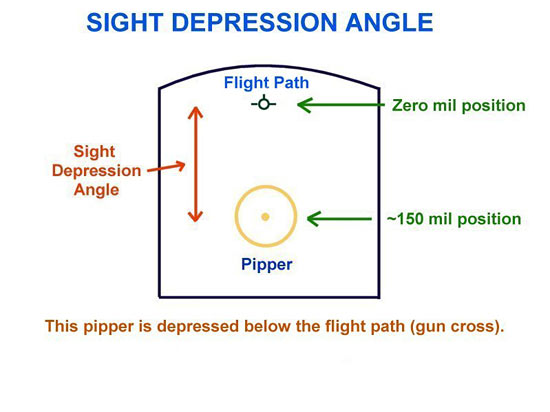
Fig 17 – Sight Depression Angle
For the typical weapons delivery, this angle is relatively small…no more than ten degrees or so. Because of this small value in degrees, another unit of angular measurement is used. This unit is the milliradian, or ‘mil’ for short (for you scientific types, one degree is about 18 mils!). Gun sights are usually calibrated in mils.
Let’s refer to Figure 2 again. This picture depicts the situation we see in many of today’s sims…one in which the gunsight is on or close to the roll or longitudinal axis of the aircraft. At the usual attack speeds, this axis and the flight path marker are essentially the same. Now, this is not technically correct in many cases (because of the effect that angle of attack has on the position of the roll axis as compared to the flight path)…but, for most of our sims, this is how the gunsight / HUDs are portrayed.
Moreover, in today’s sims, the gunsight is fixed in this position…meaning that the gunsight is not adjustable (capable of being depressed) by the pilot. Note: This discussion is about the basics of manual weapons delivery…this info is not intended to be used with reference to CCIP (Continuously Computed Impact Point) delivery systems where the pipper is free to move about the HUD.
Let’s go back now to Figure 15. There are math formulas that are used to compute the angular difference between the flight path marker and the pipper position. That value is expressed in mils…for example, let’s say the value is 150 mils. The real world pilot has a knob on his gunsight that he turns clockwise to increase the pipper depression. The pipper originates at the ‘zero’ position (for simplicity, we’ll say this is the longitudinal axis…we often think of this as the ‘nose’ of the aircraft…also known as the fuselage reference line or FRL). When the pilot turns the depression knob, the pipper moves down from the FRL. This called ‘cranking mils.’ The pilot refers to his gunnery tables for the mil depression value for a given dive angle, airspeed, and release altitude. These tables are different for each type of weapon. He then ‘cranks’ that number into his gunsight using his mil depression knob…now he’s ready to go to war!!
Well…maybe!! Let’s just stop for a moment and reconsider what we have just covered. Essentially, what we have learned is that the actual sight picture for the proper release point is not with the pipper in the position that we typically see in many of our sims. The pipper should not be on the ‘nose’ as it is depicted in sims that do not display a CCIP…as in most WW1, WW2, and Korean War sims. Instead, the pipper is actually depressed somewhere below that point. And we learned this depression value varies with weapon type and release parameters. So far, so good. This has been the easy part…from now on, the plot thickens!!
Related Posts:
Related posts:
 Air To Ground Basics – Bombing Page 5
Air To Ground Basics – Bombing Page 7
Air To Ground Basics – Bombing Page 8
Air To Ground Basics – Bombing Page 5
Air To Ground Basics – Bombing Page 7
Air To Ground Basics – Bombing Page 8
 Air To Ground Basics – Bombing, Part Two Page 2
Air To Ground Basics – Bombing, Part Two Page 5
Air To Ground Basics – Bombing, Part Two Page 6
Air To Ground Basics – Bombing, Part Two Page 8
Air To Ground Basics – Bombing, Part Two Page 2
Air To Ground Basics – Bombing, Part Two Page 5
Air To Ground Basics – Bombing, Part Two Page 6
Air To Ground Basics – Bombing, Part Two Page 8
 Air to Ground, Part Three – Rockets and Guns Page 2