Figure 1 illustrates the TDZ for a Mk 15 torpedo at its 26.5 knot setting against a 30 knot target. The arming distance is 450 yards and the maximum range is 15,000 yards.
Figure 1 – TDZ for a Mk 15 Torpedo at the 26.5 knot setting against a 30 knot target.

Aiming Problem
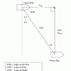
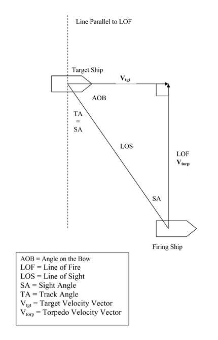
For a straight running torpedo, the aiming problem is actually a simple two dimensional interception problem. Barring a malfunction of the torpedo’s propulsion system, the problem is simplified by the fact that the torpedo maintains a constant speed. In addition, the torpedo depth control system hopefully keeps the torpedo at a constant depth, so gravity effects are not a consideration. Figure 2 shows the geometry of the torpedo aiming problem. To solve the aiming problem we need to know the target’s course and speed, the torpedo’s speed, and our location relative to the target’s line of motion.
The line between you and the target is called the Line of Sight (LOS). If the target is moving we obviously need to shoot ahead of the target in order to intercept it. The direction we shoot the torpedo in is called the Line of Fire (LOF). The angle between the LOS and LOF is called the Sight Angle (SA). SA is our “lead” angle. Finally, the angle between the target’s line of motion (or velocity vector) and the LOS is called the Angle on the Bow (AOB). AOB is measured from 0° (dead ahead of the target) to 180° (dead astern of the target), with AOB = 90° meaning you are on the target’s beam. AOB is usually given a designator to denote which side of the target you are on, e.g., “AOB: 125° Port.”
The sides of the triangle representing the target’s motion and the torpedo’s motion are vectors. As such they must be drawn in their correct directions, and their lengths must be in correct proportion the each other. Solving for SA is a simple trigonometry problem with the length of two sides and one angle known. The solution for angle SA is given by:

Here, (Target Speed) and (Torpedo Speed) must be in the same units (usually they are given in knots, although any compatible speed units could be used). Note that if (Target Speed) = 0, SA = 0° (of course, (Torpedo Speed) > 0).
I can hear the groans now — “Do I have to calculate this on the fly?” The answer is NO. Your F12 Torpedo Director station calculates this for you.
If you draw a line parallel to LOF through the present position of the target, you’ll notice that the angle between the LOS and the line parallel to LOF is the same as SA. This angle is called Track Angle (TA). TA + AOB give the angle between the target’s motion and the torpedo’s motion, or in other words, the angle of impact. Ideally you want the impact angle to be 90° as this maximizes the target’s length presented to the torpedo, thus maximizing the chances of a hit. If the impact angle is 0° or 180° then only the target’s beam is presented to the torpedo. A ship’s beam is typically 1/9 to 1/6 of its length. This means a “Down the Throat” shot (impact angle = 0° ) or an “Up the Kilt” shot (impact angle = 180° ) has about 1/9 to1/6 the probability of hitting as a beam shot (impact angle = 90° ), all other factors being equal.
Other items to note:
- The firing ship’s course and speed are irrelevant to the aiming problem. Note — this is opposite to air-air weapons employment, where the velocity vector of the launch platform has a large influence.
- The firing ship’s heading relative to the LOF only determines if the LOF is in a clear arc for the torpedo launcher.
- Solving the aiming problem says nothing about whether or not your torpedo actually has enough run time to reach its target. You must be in the TDZ or the torpedo will not hit its target.

