by Guest Writer Erik “EinsteinEP” Pierce
Just Push the Button
Imagine driving a car at a constant speed around a perfectly circular track. To make the constant turn, you have to hold the steering wheel in the proper position, turning it against the straightening tendency of the wheels on the road surface. If, because of the size of the track, the speed you were driving, etc., the required force was 50 lbs (~23 kg), or more, how long do you think you could keep this up before your arms felt like they had turned to rubber?
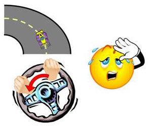
Driving a Circular Track
Now imagine that you were to drive the same course in car with a spring installed to the steering column that pulled the steering wheel in one direction. If we designed the spring so that it had just the right tension and was installed in just the right place, the spring could apply all the force needed to keep the wheel in the right position. You could literally drive hands-off all the way around the course. In reality, you would still need to provide minute corrections as the car’s heading was perturbed by the uneven road surface, wind, etc., but the effort would be minimal and you could probably drive until you ran out of gas without your arms giving up on you.

Driving a Circular Track with a Spring
If you were driving in any condition other than the one that the spring was designed for (faster or slower, bigger or smaller track, straight road, etc.), either the spring wouldn’t be helping enough or you’d be fighting its input. However, if a spring were installed that allowed you to adjust tension in real-time, then you could minimize the control force needed for any driving condition. This is the essence of control system trim.
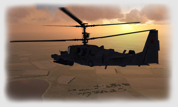
Over the years, aircraft designers have come up with some very clever methods to implement trim, from springs and weights to tabs and cables and pulleys to complex computer algorithms and electronic servos. Some methods, like the one used in the Kamov Ka-50 helicopter simulated in the DCS: Black Shark simulation, are much more complicated than our spring example, and require additional explanation and some hands-on experimentation to really understand.
In the Ka-50, just like in our spring example, control system trim is accomplished by adjusting stuff “behind the scenes” to the pilot so that the pressure needed to be applied to the flight controls is reduced to zero. The actual workings of the Ka-50’s trim system (aka the Trimmer) involve electromagnets, hydraulic controls, and a bunch of other “magic” stuff, but you don’t need to understand these mechanics to know how to use the Trimmer.
No Easy Explanation
If a pilot finds they have to constantly hold back pressure on the cyclic control stick to keep the Ka-50’s nose at the right attitude, they can press (then release) the Trimmer button while holding the cyclic steady in a position that gives the desired attitude. This action causes the control system to readjust itself, just like the spring with adjustable tension in our previous example, so that no additional force is required to keep the stick in that position. This is referred to as “trimming”, “re-centering”, or even “re-zeroing” the controls. Whatever you choose to call it, it means that you don’t have to hold pressure on the controls to maintain the desired attitude for a given flight condition.
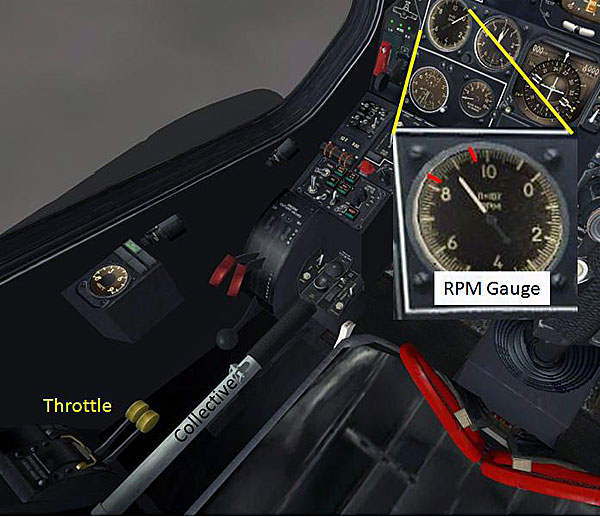
There is only one Trimmer button. Unlike a fixed wing airplane, there are no separate trim controls for the pitch, roll, and yaw axes. Pressing the Trimmer button trims ALL the attitude axes at once: cyclic forward/back, cyclic left/right, and rudder left/right. The fact that the rudder pedal position also gets trimmed is a big surprise to a number of Ka-50 pilots-in-training, who are usually expecting only the cyclic position to be trimmed. This results in mass confusion and vicious and unfounded lies about the Trimmer’s usefulness, sexual preferences, and legitimacy of birth. Note that the collective is not affected by the Trimmer. The collective lever is held in place by a friction lock called the collective brake that is released by a spring-loaded handle near the grip, so complicated trimming systems need not apply.
In our home cockpits, we generally don’t have hydraulic systems controlling our joysticks and many of us don’t have Force Feedback sticks, so the DCS Ka-50 trim system can feel counter-intuitive at first. We’ve all had more than one experience where the helicopter seems to have a mind of its own, yawing, pitching, or rolling in ways we did not expect after we use the Trimmer. A little explanation should clear up what’s really going on.
Moving the joystick away from center is like pulling or pushing on the virtual cyclic control stick. If we hold the stick forward, say 20 degrees from center, the virtual cyclic is pushed forward with some corresponding amount of force. If we press and then release the Trimmer button, the force required to hold the virtual cyclic in its current position goes to zero, due to the equalizing action of the Trimmer system.

Before Trimming
After Trimming
However, right when we release the Trimmer button, we’re still holding the joystick forward. The simulation interprets this as a force being applied to the virtual cyclic and, since now there’s no force required to keep the cyclic where it is (due to the Trimmer action we just completed), the cyclic bumps forward even more. The catch is that if we’re using the Trimmer properly, the joystick will *always* be off center just after we release the Trimmer button, which means there will *always* be a bump!
Although the programmers at Eagle Dynamics do think very highly of us, they know we can’t move the joystick from the desired trim position to center instantly, so they’ve made the simulation ignore control inputs until we re-center the controls (both the cyclic stick and the rudder pedals!), which completely avoids control “bump”. Neat, eh?
Before patch 1.0.1, the Trimmer ignored control inputs for a fixed amount of time, which resulted in a lot of control bumping and pilot confusion. Control bump is gone in the new method, but some pilots are now reporting that their controls occasionally “freeze” or become unresponsive after using the Trimmer. This is most likely caused by the pilot inadvertently failing to re-center both the cyclic AND rudder pedals after using the Trimmer, but you can opt to return to the old Trimmer method via in-game options, if you so choose, to avoid this control freeze possibility and live with control bump.
Whichever implementation you choose, just remember that the rudder pedal positions are also trimmed in!
Now that we have the basics of the Trimmer understood <fingers crossed>, here’s a brief walkthrough of how this all works in DCS: Black Shark without a Force Feedback joystick.
It’s important to know that the Trimmer and the autopilot are two distinctly separate systems. We’ll talk more about the autopilot in a later essay, but when experimenting with the Trimmer, turn the Flight Director override on to disable the autopilot’s responses. You’ll get a much better feel for what the Trimmer is doing this way. The Flight Director override has been enabled in this example for demonstration purposes.
In this example, the pilot has already established a hover and has trimmed the controls to maintain the hover with minimal control input.
Trimmed for Hover
Ready to begin the mission, the pilot pushes the joystick forward to pitch the nose down and accelerate his helicopter forward. From practice he knows putting the nose at 10 degrees down will get the desired acceleration rate, so he applies enough forward pressure on his joystick to maintain this attitude.
Pitch Down for Forward Flight
Once the nose is steady right where he wants it, he presses and then releases the Trimmer button and quickly re-centers his controls.
Trimmed for Acceleration
He carefully watches the helicopter’s attitude as the control system trim takes effect and as the changing flight conditions affect the helicopter’s dynamics, re-applying Trimmer as needed to maintain the desired attitude. Throughout the maneuver, the pilot uses the collective to achieve the desired climb rate, but use of the Trimmer has no effect on this input.
As the helicopter begins to pick up airspeed, increasing amounts of right rudder and left cyclic are needed to maintain level coordinated flight, due to the unique aerodynamics of the Ka-50 contra-rotating coaxial dual rotor system. At first the pilot applies the required corrections via the joystick and rudder pedals, but, as the amount of the correction needed increases, he re-applies the Trimmer, re-centering the joystick and rudder pedals each time. After the helicopter reaches the desired cruising speed, the pilot only has to provide minimum pressure on the controls to keep the aircraft in stable steady-state level coordinated flight.
As the pilot approaches his destination, he pulls the joystick back to raise the nose to slow the helicopter. He uses the Trimmer again to maintain the desired deceleration attitude. As the airspeed drops off, less right rudder and less left cyclic are needed to maintain coordinated flight, but the Trimmer is still applying the same control inputs that were previously set during cruise. The pilot applies some left rudder to keep the ball centered and enough right cyclic to maintain level flight and employs the Trimmer, again re-centering the controls. He continuously re-trims during deceleration, pre-empting any large control inputs. As the helicopter slows down, the amount of control force he needs to input are much smaller than if the pilot had not used the Trimmer, and he can focus more energy on the finesse required to enter a hover instead of fighting the controls. By the time he has established a steady hover over his destination point, the rudder inputs have been trimmed back to center, there’s no more side cyclic trimmed in, and the helicopter response is smooth, stable, and predictable.
There are three keys to understanding the Ka-50 Trimmer: practice, practice, and practice. While you’re learning the Trimmer and how it affects the flight controls, turn all four autopilot channels on (which enables stability augmentation, to be discussed in the next part), but also turn on Flight Director. With the Flight Director override (see the upcoming Part 2 of the autopilot discussion), autopilot control feedback to the flight controls are disabled so all the rotors see is pure Trimmer and pilot inputs. When you find you have to apply a constant control pressure use the Trimmer to hold that pressure for you. Just don’t forget that the Trimmer continues to hold that pressure, whether or not you still want it! Only regular and continuous use of the Trimmer over changing flight conditions will result in a stable platform with an intuitive response.
Other articles in the Series:
We want your Feedback. Please let us know what you thought of this article here.
Related posts:
 A Stick and Rudder Man’s Guide to DCS: Black Shark Page 2
 DCS: Black Shark and Coaxial Rotor Aerodynamics
 DCS: Black Shark – Autopilot: Part 1
 DCS: Black Shark – Autopilot: Part 2
 DCS: Black Shark English Version – Part 1 Page 6
DCS: Black Shark English Version – Part 1 Page 7
DCS: Black Shark English Version – Part 1 Page 6
DCS: Black Shark English Version – Part 1 Page 7
 DCS: Black Shark English Version – Part 2 Page 5
 DCS: Black Shark… Technical, Simplified