
by Andy Bush and Leon “Badboy” Smith
In this article, Leon Smith and I will present two techniques for dropping bombs, firing rockets, and strafing with the cannon in SFP1. We are responding to the many posts that we have seen regarding the difficulty that SFP1 players are having in getting their weapons on target.
Introduction
We begin with an introduction that identifies the problem in the sim, and then uses real life weapons delivery academics to explain the things to do and not do in the sim.
What Is The Problem?
The problem is quite simple. If the player aims his gunsight aiming symbol at the target and then releases or fires his weapon, he has only a small chance of actually hitting the target.
Is this pilot error or is the game somehow “programmed” incorrectly? The answer is both. The typical pilot is not using the aiming symbol properly…and the sim AI does not award a hit when the symbol is used as in other simulations. And there is the rub…you folks are trying to drop bombs or fire rockets in this sim much as you have in other sims. Why is this an issue?
Two reasons. One is that modern jet sims typically model a computer aided weapons delivery system, known as a CCIP (continuously computed impact point) system. When using a CCIP aiming symbol, all the pilot has to do is fly the aiming symbol over the target and release the weapon. Normally, he can expect a hit. The second reason is that folks are used to sims that award a hit using a relatively wide “hit bubble”…one that allows the pilot to fly a wide range of delivery parameters and still expect a hit.
This is not the case in SFP1. There is no CCIP in SFP1 simply because these aircraft did not have that type of weapons delivery system. Secondly, in SFP1, the weapons impact point is very sensitive to pilot delivery parameters…close in SFP1 won’t hack it!
Instead of a CCIP-type weapons aiming system, SFP1 uses the older “manual” system. We’ll begin our discussion with a brief explanation of the manual delivery procedure.
Manual Weapons Delivery
I’m not going to present a full discussion of A2G theory in this article…I’ll only refer to things that directly affect how you fly this sim. If you would like more info on the academics of manual weapons delivery, please see the A2G series in SimHQ’s Air Combat Corner.
Let’s start with a definition of manual bombing. It is simply the procedures and techniques that allow the pilot to compute a weapons release point without the aid of any type of computer. In manual weapons delivery, the pilot must use a very limited set of cues to first determine how to initially aim his plane at the target and then determine the actual release point.
To do this, the pilot uses two sets of cues. The most important is his gunsight aiming reticle, often referred to as the “pipper”. Next, the pilot has his aircraft instruments from which he reads his conditions of flight….altitude, airspeed, and dive angle are the most important of these.
To understand manual bombing, the pilot has to understand the basics of weapons ballistics…let’s take a moment to check this out.
Weapon Ballistics
Every weapon that is dropped or fired from a plane is affected by gravity. When the weapon is released, it moves both forward and down. Forward due to the velocity of the releasing aircraft and possibly, in the case of rockets and bullets, due to their own propulsion. And then down due to gravity…how much “down” is a function of the time from release to impact.
Here is the significance of this. Let’s imagine a plane in a dive at the ground. If it were to maintain a constant dive angle, we could present its flight path as eventually intersecting the ground at a “crash point”.
If a weapon is dropped or fired from that plane, it will move forward along the flight path but will also have a downward vector due to gravity. Because of this, the weapon will never impact where the flight path intersects the ground but will hit somewhere short of that point. This is true of rockets and bullets, as well as bombs.


From this observation, we arrive at this conclusion. No weapon will ever hit the point at which the aircraft’s flight path is aimed.

And that, folks, is manual A2G in a nutshell. For conventional “dumb” weapons, if you aim right at the target, you will never hit it!
So where do we aim our plane? The answer is that we aim our plane at some point past the target. We use standard clock code to describe this by saying that we aim our plane past the target…or at its 12 o’clock.
Sounds good…but how exactly do we “aim” the plane? You do this by visualizing the aircraft flight path on your forward view. Let’s talk about that for a second.
Estimating Your Aircraft Flight Path
We know that an aircraft has three axes of motion…pitch, roll, and yaw. When it comes to weapons delivery, the most important of these is the roll axis. Why? Because the main problem in weapons delivery is getting your flight path (ground track) to intersect the target. This is an aircraft heading control problem…flying a heading to achieve the desired ground track…and roll is the control that we use to control heading.
We do that by orienting our lift vector in the direction we want to go. Then we use pitch (backpressure) to move our nose in that direction. The hitch here is that we need a reference on the forward view that we can visualize as the “nose” of our aircraft. We then roll and pull as needed to get that “nose” reference where we want it.
To roll the plane, we need a reference for the roll axis. As we roll, we can look through the forward view (usually the “HUD” area) to estimate that point that we seem to be rotating around. If you were to do a complete 360-degree roll, that point (the roll axis) would be stationary on the “HUD” while everything else rotated around it. Note: none of the SFP1 aircraft have “HUDs” as such. The correct term is “combining glass”. Most of us are familiar with the term “HUD”, so I’ll use it in this article, just to simplify things a bit.
The problem in this sim is that the roll axis is difficult to identify when maneuvering…as a consequence, precise flight path control is more of a problem. To help with this, I suggest these ideas:
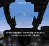
As an approximation of the roll axis, I recommend using the top of the “HUD”. This reference will be “close enough for government work” for the four fighters in the sim.
When maneuvering to aim your aircraft in weapons delivery, make your maneuvers smooth and unaggressive. Make your pitch and roll inputs small and avoid rapid and large bank changes.
As a general statement, do not use the gunsight reticle as your roll axis reference. In all of the aircraft, the reticle tends to be “below” the actual roll axis. If you use the reticle as an aiming reference, you will often end up overshooting your desired roll out point. (See the discussion of “pendulum effect” in the A2G articles.)
At this point in our discussion, we have noted the need to aim “past” the target, and we have seen that the top of the “HUD” is a good approximation of the roll axis (the reference that we use for aiming the plane). The outcome of this is that we roll out with our “nose” (the top of the “HUD”) aimed at the 12 o’clock of the target as we begin out approach to the target.
If this is the case…that we aim not at the target but past it…then how does the gunsight work? How does the “pipper” “work”? That answer leads us to our next subject…the depressed gunsight reticle.
The Depressed Gunsight Reticle
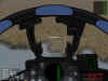
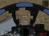
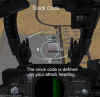
In the A2A mode, the gunsight reticle is in the “caged” position that allows the sight to be used for aiming the gun and A2A missiles. This caged position is located in the upper portion of the HUD area. As a result, the separation between the roll axis (top of the HUD) and the caged position is minimal. When you select A2G in SFP1, the gunsight reticle drops down a little in the F-104 and F-4. This “dropping down” is called “depression”, and in these fighters was manually controlled by the pilot using a knob on the gunsight control panel. The unit of depression was the “mil”. Note the mil setting dial on this screenshot set at 50 mils.


In real life, the amount of depression used corresponded to the delivery parameters selected by the pilot. Each weapon type, each dive angle, and each release altitude and airspeed had its own unique depression setting…consequently, for a particular type of delivery, the pilot would dial in “x” mils of sight depression.
The amount of depression was directly related to the difference between the aircraft flight path and the flight path of the weapon. Because they were powered at release, rockets and bullets had the least sight depression. Steep, fast, and low altitude bomb releases had relatively low mil values because of the minimal time of flight. Conversely, low angle, slow speed, and higher altitude releases require larger depression settings. Additionally, high drag weapons tended to have larger mil settings because of the effect of drag on their flight paths.
But in SFP1, we only have one depression setting…and only two of the fighters have sights that depress. This may be unrealistic, but we can’t worry about that too much…we need to find a way to make the sight “work”! We have found from experience that aiming the pipper at the target and then releasing the weapon seldom results in a hit.
Is it possible to use the existing gunsight in the sim? Yes…as it turns out. Leon and I have done a little experimenting and have come up with two different techniques that might work for you. We’ll start with Leon’s ideas first.
Leon Smith – Tips For Dive Bombing
Employing the Mk82 in Strike Fighters
The Mk82 bomb consists of a simple iron casing filled with explosive and a mechanical impact fuse. It is a good general-purpose bomb effective against hard and soft targets, but requires a direct hit to be effective against enemy battle tanks. This weapon can be delivered with the use of the adjusted Gun Sight on the HUD. The display is fixed and therefore represents the convergence of the line of sight to a point on the ground, with the impact point of the bomb, for a particular attack profile.
A typical attack profile will look like this.

The question is, what value of altitude, velocity and range from the target make up your correct release parameters for this weapon? Because dive-bombing in general has been covered in depth in other articles, we will provide the answer to that question in this article by demonstrating the appropriate technique in the Strike Fighters simulation.
You will shortly see that we recommend releasing the bomb at a dive angle of 27 degrees, a speed of 535KIAS at an altitude of 4000ft, as a solution to the sighting problem. That will provide a combination of range, speed, time-over-target and pull out altitudes that will maximize your bombing accuracy while minimizing the risks. Your results will depend on good reflexes, hand eye co-ordination and timing. The good news is that these parameters are reasonably tolerant of small errors and good results can be achieved against relatively large, stationary targets in Strike Fighters, with a modest degree of skill after some brief initial practice.
Achieving direct hits on small targets such as tanks and other vehicles is slightly more difficult. This makes the Mk82 ideally suited for targets such as hangers, control towers and other ancillary buildings and runway surfaces… So, how is the weapon employed?
Here are two examples of exactly the same dive-bombing procedure that is easy to reproduce and gives 100% results. The procedure is easy to reproduce, because the altitude and speed for the approach have been chosen so that the early stages can be flown using the autopilot. When selecting autopilot, my aircraft leveled off at an odd altitude of 9837’, at a speed of 475KIAS and a throttle setting of 58%. These are the parameters for this article only because of this autopilot idiosyncrasy. Should you fly this maneuver manually, minor deviations from these parameters probably will not affect the technique.
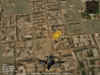
The first strike mission requires the destruction of a communications building. In the screen shot below you can see the primary target has been selected and you are almost ready to begin your turn towards the target.

The next image shows the turn to the attack heading, commencing at 15nm. Use a low g maneuver here to conserve energy.

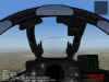
Once you have the target at 12 o’clock, begin your run into the target by ensuring that you hit the correct flight parameters. You need about 10,000’ and 475kts. Those conditions can be achieved by using the autopilot or by flying manually.
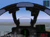
In the next shot you can see that those parameters have been achieved and with around 8nm to go, select A2G mode and ensure that the Mk 82 bomb is selected as well. Continue to fly the approach straight and level.
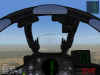
When the range to the target is just over 3nm reduce the throttle to zero and push the nose over smartly until the bombsight lies directly over the target. The figure below shows the range at 3.1nm, that is the right moment to cut the throttle and push over. This will result in the correct dive angle when you reach your release altitude.
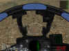
The next figure shows what you should see the moment before the bomb is released. You are just over 4000ft and 1nm from the target with the gun sight in dive bomb mode placed directly over the target. As the altitude passes through 4000’, the range will change to 0.9nm and you must release the bomb at that point.
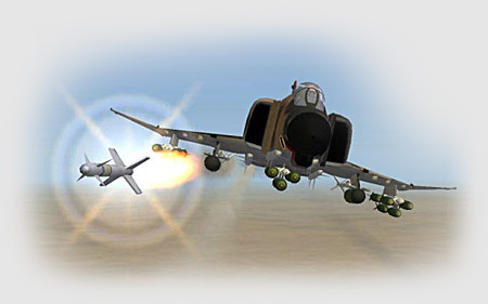
Let’s watch the following events from two perspectives. The following sequence of screenshots follows the bomb to its target.


The next sequence shows the same release from an external perspective.
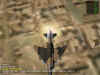
Notice that the throttle setting here was pulled back to zero during the dive, from the moment just prior to pushing the nose over! Don’t forget to push the throttle back in during your pullout and egress!
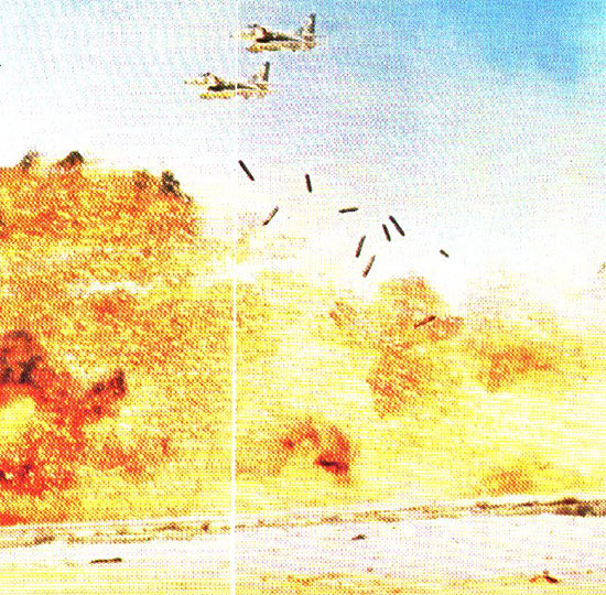
With the communications building gone, let’s try the same procedure on an oil tank. This time, the sequences of shots are presented without commentary.

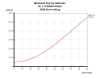
After flying a number of these missions several times, without wasting a single bomb, the conclusion is that this attack profile has a high degree of repeatability. Here is the trajectory shown from the moment the bomb is released.
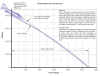
One of the risks associated with a diving approach to the target, is the tendency for inexperienced pilots to extend their approach while attempting to line up the target in the sight. The risk of course being that they won’t allow enough time to pull out of the dive before flying through the target’s blast radius, or even worse, before impact with terra firma! The diagrams below shows the safe pull out altitudes for various dive angles for a heavily loaded F4 at the speed we have used in our attack profile.
This chart shows that for a 30 degree dive at 535KIAS we can clear the 500’ blast radius by pulling out at about 1200’, in fact you can initiate your dive recovery the moment the bomb is released, and at least by 3000’, so there is an adequate margin of safety in this attack profile.
Related Posts:
Related posts:
 A2A Weapons Delivery In Strike Fighters
 Page 2
A2A Weapons Delivery In Strike Fighters Page 3
A2A Weapons Delivery In Strike Fighters Page 4
A2A Weapons Delivery In Strike Fighters
A2A Weapons Delivery In Strike Fighters Page 2
A2A Weapons Delivery In Strike Fighters Page 3
A2A Weapons Delivery In Strike Fighters Page 4
 Air To Ground Basics – Bombing Page 5
Air To Ground Basics – Bombing Page 6
Air To Ground Basics – Bombing Page 5
Air To Ground Basics – Bombing Page 6
 Air to Ground, Part Three – Rockets and Guns
 Techniques For Weapons Delivery In SFP1 Page 2