The Lead Angle and Its Effect On the Gunnery Problem
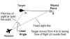
First of all, what’s the lead angle? In simple terms, since the rounds that we fire take some small amount of time to reach the target, whenever we have any deflection at all, we must aim in front of the target. The angle between our nose and our line of sight to the target is the lead angle, and the major components of that angle are lead for target motion and gravity drop.

I can’t resist throwing in a formula to drive you all nuts! Here it is. This is the formula for what is referred to as “kinematic lead”…another way of saying “lead for target motion”. I’m mentioning it so that you can appreciate the variables that go into the lead angle problem. Kinematic lead only deals with the target movement across our flight path…it is just one part of the total lead angle solution. But it is usually the largest part of that angle, and taking a look at how it is computed allows us to better understand how angle off figures into the “big picture”.
L = Vt x 1000 x Sin@ / Vm
L is the lead for target motion (in mils).
@ is the deflection angle (angle off in degrees).
Vt is the velocity of the target (feet/sec).
Vm is the average velocity of the round from firing to impact in feet/sec (this includes your velocity).
Several things become obvious when looking at this equation. Lead becomes greater as airspeeds increase. Lead increases as angle off increases. Lead increases as range increases (because of reduced average muzzle velocity).
It is possible to assume some variables and compute this value. The formula produces a lead angle measured in mils. When I was a student in F-4 training, we flew the F-4C which did not have a lead computing sight. Our sight could be manually depressed from its fixed position. When we flew our A2A gunnery missions against a towed target, we computed a mil setting based upon the expected parameters. We then dialed that setting into the sight. The idea was to track the target with the pipper elevated for gravity drop.
Did this technique work? Not unless you were really lucky!! I much preferred to put the sight at its fixed position and estimate the lead…just as we do in AH…or any sim that uses a fixed sight.
Using the Gunsight To Estimate the Correct Lead Angle
Let’s now think of what we would need in a gunsight to help us measure the lead angle. Two big things come to mind. We need a set of visual references on the sight located at some distance from the pipper. And we need some way of scaling these references so that we are measuring the lead angle accurately.
To keep this as simple as possible, I’ll focus in on angle off as the primary variable in this discussion. Certainly, range, relative speeds, and type of ammo all contribute to the problem, but if we try to include these, we end up with a situation where nothing can be approximated with any clarity. My objective is to give you some easily recognized visual cues to help you estimate the required lead angle as a function of angle off.
Let’s look at three situations…low, medium, and high angle off…and the approximate lead required.
Anytime we start crunching numbers, we need to identify our parameters…so here are mine. I’ll use a P-51 with its .50 caliber machine guns. Both it and the target are co-speed. I’ll assume an average range of 1000 feet…but note that range itself is not in the lead equation. But it is still there…in the form of reduced average muzzle velocity (the round slows down as range increases). For our purposes, I’ll subtract an arbitrary amount for this decrease in muzzle velocity. Here are some typical values for two sets of speeds:

So much for the rocket science! All of this mumbo-jumbo about mils doesn’t mean anything unless we can put it to use in the heat of battle. How do we do that? We begin by finding a way to estimate angle off. We decided to break angle off down into three types (low, medium, and high). Now we need a way to recognize these positions in our sim. Do I have a recommendation? Of course! That’s what this article is all about!

Here it is! We’ll use the relationship of the target rudder to the target’s fuselage and wing. Picture yourself looking at the target from the rear. The target rudder will intersect some other part of the target fuselage/wing as you view it.
If you see the rudder lined up with the target’s nose (or there abouts), I’ll call this “low angle off”. If the rudder is superimposed about half way out the target wing, I’ll call that “medium angle off”. And if the rudder is all the way out to the wing tip…well, that’s “high angle off”. Here’s what it looks like:


Once we can recognize angle off, we then need a way to estimate the approximate lead angle that corresponds to that angle off. NOTE: I say “approximate” because of the highly variable nature of these computations. I cannot give you a reference for each and every tracking position! But, if you begin with these approximations and then fine tune your solution through practice, you should do OK. These recommendations are only a starting point, not the final answer!
Let’s begin with the values shown in Figure 18. We want to find a way of measuring and then displaying these mil lead points on our fixed sight. And to do that, we go back to the concept of what a mil is.
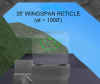
A mil (short for milliradian) is a small angle…about 1/17 of a degree. Since we don’t take protractors into the cockpit, we need another way of visualizing the magnitude of the mil unit of measurement. A very convenient way of doing this is to use the approximation that one mil equals one foot at 1000 feet. Since this is a linear angular relationship, we then use this concept to relate wingspan in feet to mils. For example, let’s assume a wingspan value of 35 feet…then this wingspan of 35 feet would equal 35 mils at a range of 1000 feet…and at 2000 feet range, the wingspan would equal about 17 mils. The next figure shows this.

This mil versus range measuring technique can be used to estimate lead angles. We begin by agreeing to a standard size of target…we can do this since WW2 fighters were all fairly similar in size…at least close enough for the lead angle approximations that we are going to come up with. We may use either wingspan or fuselage length as they are nearly equal in most WW2 fighters. Wingspan is most commonly used because, in a typical gun attack from the aft quarter, this is the one aircraft dimension most easily seen. In certain angle off situations, fuselage length is a good substitute.
Having selected a standard (I’ll use 35 feet for mine), we then use that standard along with our mil/feet relationship to come up with a technique to estimate lead angles. To do this, we make one big assumption…and that is that the lead angle in mils does not change significantly for the typical firing ranges that we are going to be dealing with…for the speeds and ranges we will encounter, this assumption is “close enough for government work”! Now, we take this, add some typical angle off situations, throw it all into a bag and give it a good shake! Out of it comes this chart that shows how aircraft size can be used to estimate lead angle requirements:

Note – In arriving at these numbers, I rounded off quite a bit in the interest of simplicity. Changes in speeds and muzzle velocities can effect these calculations. I used the .50 caliber machine gun as a reference…other guns with lower muzzle velocities will result in greater lead angles. No matter. Use these techniques as a starting point, then fine tune your own sighting solution.
In the case described, a 15 degree angle off lead equals a little less than two wingspans. It’s important to note that most rear aspect gun attacks are taken at angles off of 10 degrees or less…so we could visualize a lead of one to two wingspans in this situation. In our previous discussion, we mentioned three angle off situations (low, medium, and high). This is what the lead would look like for these situations.


All that is left now is to build a sight that can be easily used. Using our example, we could design a sight with a feature that allows us to recognize a 35’ wingspan at 1000’ (and 1000’ is pretty close to our desired convergence range of 300 yards!). We would then use this feature as a cue to establish the pipper in lead. For example:
But, you say…what if I wanted to try this technique in AH…could I do it? You betcha! First, you design the sight with the feature that you will use to estimate lead…I like the circle with a pipper in it…that’s what I used when I flew RL fighters…and it’s a design found in most fighters since the end of WW2. Let’s go through the steps one by one.
How To Design And Adjust A Fixed Gunsight In Aces High
1. Why?
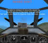
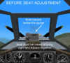
First off…why would you want to do this? Several reasons. One…you just want a different looking sight…it’s a free country! Why not?!! Second reason…I want to relocate the pipper position on the HUD in order to improve my ability to look over the nose…this can help when trying to track a target at high angle off. One way to do this is to move the pipper “up” to the top of the HUD area…more on this later. We then use the Page Up/Down keys to, in effect, raise the seat height in the cockpit to realign our gunsight with the tracer path.. In the next two figures, you will see the additional area that is visible when the forward view is ‘raised”.


And, lastly, we may want to have a gunsight than can be used to estimate range. So our three reasons are based on simple esthetics, over-the-nose visibility, and convenient ranging. Sounds good to me!
2. Designing a New Gunsight
Let’s begin by redesigning our sight. Use any graphics program to do this. I use Paint Shop Pro…a free demo is available from here. As a starting point, use one of the sights in the AH sight folder. Make a copy of it to save. Then use the graphics program drawing tools to erase and redraw your specific sight details. The program will only use the two colors in the original sight .bmp file, so don’t worry about matching the colors!
In the Aces High library, there are a number of gunsight designs to pick from. Perhaps you see one that is not quite “right” for your tastes…maybe it has too much or too little detail. No matter. Use it as a basis for designing your own sight. Once you have your design decided upon, you can move on to the next step.
3. Increasing the Over-The-Nose Visibility
To help me improve my “over the nose” visibility, I design or adjust an existing sight so that the pipper is at or near the top of the HUD. My objective is to maximize the amount that I can “raise” my forward view.
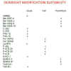
Note – not all AH aircraft have gunsights that adapt easily to modifications. The following chart indicates how well I had luck in modifying the sights in Aces High. Please experiment on your own…you may get better results than me!
4. Name it
Now, name the finished sight as “default.bmp”. AH will use whatever sight you have labeled as “default,” unless you have loaded a sight specifically designed for your particular plane (such as f4u1C.bmp). To use your new sight in the F4U1C, for example, either remove the f4u1C.bmp file from the sights folder or rename it.
5. Testing, Testing
OK. We have a finished sight. But, now, we need to make sure the bullet stream is aligned with the pipper of our new sight. We do this by loading the game and going to the off-line area. Choose whatever plane you want and start off on the end of the runway.
Zoom the sight in using the Z key. Then, fire a short burst and note the location of the tracer path to the pipper. Use the Page Up/Down keys to move the sight up or down to reposition the pipper into the tracer path. Save this with the F10 key.

Depending on the pipper location in your revised sight, you may be unable to match the tracer path to the pipper. In a number of the AH aircraft, the sight will fade out as you adjust the seat height position. You may not be able to get a “full up” seat position. I n this situation, use the Page Up/Down keys to raise the sight as much as possible and then note the tracer position on the sight.
Now, use your graphics program to lower the center reference (the pipper) until it will match the tracer path. You will have to use trial and error to compare your new sight design to the actual tracer path.
6. Estimating Range With the Gunsight
At this point we have a new sight that fires through the pipper. That’s good! But we also want a sight that is usable as a range indicator. First, determine what range you want the sight set for…usually this is your convergence range. With that in mind, let’s go flying! Takeoff and fly to one of the drone’s six o’clock. Close in to your convergence range and start the film recorder using the Alt+R keys. Try to stabilize with your pipper on the drone at your convergence range.
Turn off the recorder and exit the game to the start up screen. Select “Film” and start your film. Freeze the playback when you get to the part where you are at your desired convergence range with the pipper on the drone.
7. Calibrate
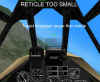
Now we are ready to calibrate the sight for our desired range. Select F1 and press the Z key to zoom in. Now, press the up/down arrow keys…notice how the sight size expands and contracts relative to the target? Great! Use the arrow keys to adjust the sight until your sight reference matches the wingspan of the drone. In the next two figures, I use a convergence range of 200 yards and exaggerate the sizing of the reticle to show the sizing technique.
Voila’! Now, you have a sight that is calibrated to indicate range. Save this position using the F10 key.
Note 1: It is likely that this sight setting may only be good for the aircraft that you initially selected. If you change aircraft, carefully check the sight out before you trust it!
Note 2: By sizing the sight using the “zoomed in” view, you will also affect the F1 zoomed out view. This may not allow you to see certain cockpit instruments, so choose this position wisely!
The Bottom Line
You can use a well designed sight…or you could use a piece of gum stuck on the windscreen…no matter. The only thing that counts is killing the bandit. In this article, I’ve laid out simple rules of thumb and techniques for A2A gunsight use. There is no magic bullet in this skill. The best sight in the world is not going to help a plumber!
Just remember that a gunsight is meant to do very specific things, based on well defined physical laws. Gunsights were not meant to look “cool”…they are best kept simple and reliable…and then to be used by a skilled pilot. Good luck!
Related Posts:
Related posts:
 Air To Air Gunnery – Theory and Application, Part Three Page 10
Air To Air Gunnery – Theory and Application, Part Three Page 5
Air To Air Gunnery – Theory and Application, Part Three Page 10
Air To Air Gunnery – Theory and Application, Part Three Page 5
 Air To Air Gunnery – Theory and Application, Part Two Page 3
 Air To Air Gunnery Revisited – Guns, Gunsights, and Convergence
 Air To Ground Basics – Bombing Page 6
 Air To Ground Basics – Bombing, Part Two Page 5
 Air to Ground, Part Three – Rockets and Guns Page 2
 IL-2 Series – Fundamentals of Gunnery Page 3